Fuel injection valve for internal combustion engines

a technology for internal combustion engines and fuel injection valves, which is applied in the direction of fuel injection apparatus, spraying apparatus, feeding system, etc., can solve problems such as guidance and sealing problems

Inactive Publication Date: 2001-06-19
ROBERT BOSCH GMBH
View PDF6 Cites 5 Cited by
  • Summary
  • Abstract
  • Description
  • Claims
  • Application Information

AI Technical Summary

Benefits of technology

The fuel injection valve according to the invention has the advantage over the prior art that the guidance and sealing is improved over the fuel injection valves for internal combustion engines known from the prior art. Disposing one pressure shoulder on the end remote from the combustion chamber of the valve body in a compensation chamber communicating fluidically with the pressure chamber and closed off on its face end by an axially displaceably guided pressure sleeve has the particularly great advantage that the compensation chamber always communicates with the pressure chamber. This assures that the pressure shoulder will always be acted upon by a pressure; it is assured that pressure differences, for instance when the fuel injection valve opens, between the pressure chamber and the compensation chamber are compensated for directly. In this way, a restoration to the closing position of the fuel injection valve is always provided--even if a force acting in the opening direction is exerted on the valve member, for instance because of a leak toward the combustion chamber, caused by a resultant pressure difference between the pressure shoulders. The valve member is advantageously formed in needle-like fashion between the two pressure shoulders and has a constant diameter. Because the valve member is embodied as a thin needle of constant diameter between the two pressure shoulders, a slight offset between the guides, formed hand by the valve member head other by the pressure sleeve, can be compensated for in a simple and advantageous way.To avoid leaks, the pressure sleeve is preferably press-fitted onto the valve member. Purely in principle, the compensation chamber can be embodied in an arbitrary way. One embodiment that is advantageous in particular with respect to ease of manufacture provides that the compensation chamber annularly surrounds the pressure shoulder remote from the combustion chamber.The high-pressure delivery of fuel to the fuel injection valve is preferably done from a high-pressure reservoir common to all the fuel injection valves, and the high-pressure reservoir can in turn be filled via a high-pressure fuel pump.The actuator for actuating the valve member is advantageously an electromechanical actuator. In particular, it is embodied as a piezoelectric actuator or electromagnet.Further advantages and advantageous features of the subject of the invention can be learned from the description, drawing and claims.Shown in the drawing are:FIG. 1, schematically in section, the lower region of a fuel injection valve for internal combustion engines that makes use of the invention; andFIG. 2, schematically in section and enlarged, the end remote from the combustion chamber of the valve body of the fuel injection valve for internal combustion engines that is shown in FIG. 1.

Problems solved by technology

One problem in such fuel injection valves is guiding and sealing the valve member in the valve body 1.
Thus particularly if the bores are not oriented exactly, or if the valve member has slight kinks, guidance and sealing problems occur.

Method used


Image

  • Fuel injection valve for internal combustion engines
  • Fuel injection valve for internal combustion engines

Examples


Embodiment Construction

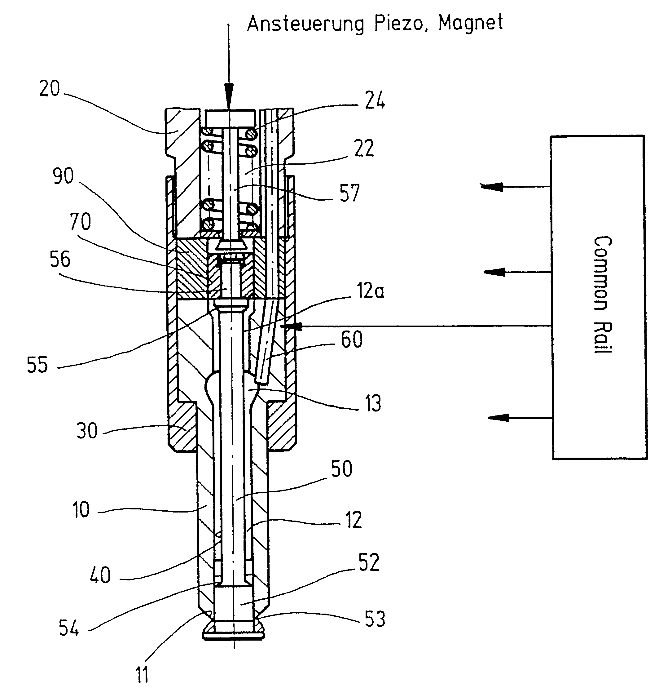
One exemplary embodiment of a fuel injection valve for internal combustion engines, whose lower portion toward the combustion chamber is schematically shown in section in FIG. 1, has a valve body 10, which is axially fastened firmly to a valve holder body 20 by means of a union nut 30.

The valve body 10 has an axial guide bore 40, in which a needle-like valve member 50 is guided axially displaceably; on its lower end, protruding into a combustion chamber (not shown) of the engine to be supplied with fuel, this valve member has a valve head 52 acting as a valve closing member. This valve head 52 protrudes out of the bore and has a conical sealing face 53 oriented toward the valve body 10; in the exemplary embodiment shown, the sealing face is formed by a seat ring mounted on the valve head 52, and the seat ring cooperates with a corresponding valve seat face 11 on the face end toward the combustion chamber of the valve body 10.

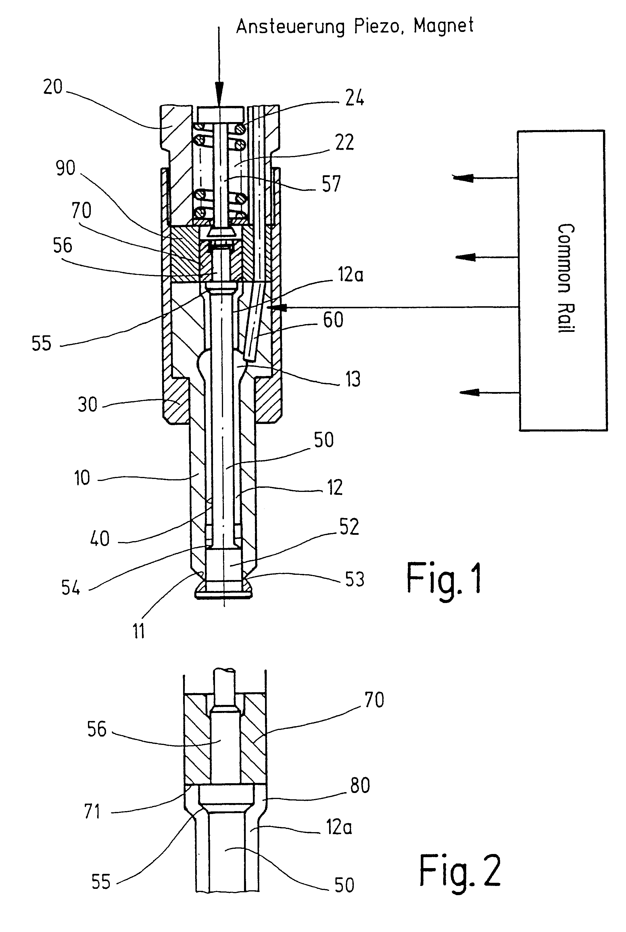
Between the wall of the bore 40 and a part of the shaft of...


PUM


Abstract

A fuel injection valve for internal combustion engines, having a valve member which is axially displaceable in a bore of a valve body and which on an end toward the combustion chamber has a valve member head. The head forms a valve closing member, which on one side toward the valve body has a sealing face, with which the sealing face cooperates with a valve seat face provided on the face end of the valve body toward the combustion chamber. An injection opening in the valve member head, which emerges from a pressure chamber, formed between the valve member and the wall of the bore, and leads away along the circumferential wall of the valve member head. The injection opening is closed by the wall of the bore when the valve member is resting on the valve seat and is opened by an outward-oriented opening stroke motion of the valve member. The valve member is actuatable by an externally controllable actuator independently of the high fuel pressure in the pressure chamber, and two pressure shoulders, facing one another and axially defining the pressure chamber, are provided on the needle-like valve member and each have substantially equal pressure engagement surface area. The pressure chamber is characterized in that one of the pressure shoulders is disposed on an end remote from the combustion chamber of the valve body, in a compensation chamber which communicates fluidically with the pressure chamber and is closed off on a face end by an axially displaceably guided pressure sleeve.

Description

DESCRIPTION AND PRIOR ARTThe invention relates to a fuel injection valve for internal combustion engines.Such an injection valve is disclosed for instance in German Patent DE 43 25 904 C2, as well as German Patent Application DE 197 16 226.6-13, which had not been published by the priority date of the present application.One problem in such fuel injection valves is guiding and sealing the valve member in the valve body 1. Thus particularly if the bores are not oriented exactly, or if the valve member has slight kinks, guidance and sealing problems occur.ADVANTAGES OF THE INVENTIONThe fuel injection valve according to the invention has the advantage over the prior art that the guidance and sealing is improved over the fuel injection valves for internal combustion engines known from the prior art. Disposing one pressure shoulder on the end remote from the combustion chamber of the valve body in a compensation chamber communicating fluidically with the pressure chamber and closed off o...

Claims


Application Information

Patent Timeline
Patent Type & Authority Patents(United States)
IPC IPC(8): F02M63/00F02M63/02F02M61/00F02M61/08F02M51/06F02M47/02F02M61/16
CPCF02M51/0603F02M61/08F02M63/0225
Inventor POTSCHIN, ROGERBOECKING, FRIEDRICH
Owner ROBERT BOSCH GMBH
Why Eureka
Try Eureka