Turbine stage in a turbomachine

a turbomachine and turbine technology, applied in the field of turbomachines, can solve the problems of reducing the performance of the turbomachine, deformation of the casing, and inability to optimize the radial clearance between the movable blades, and achieve the effect of simple, effective and economical

Active Publication Date: 2013-03-26
SN DETUDE & DE CONSTR DE MOTEURS DAVIATION S N E C M A
View PDF21 Cites 6 Cited by
  • Summary
  • Abstract
  • Description
  • Claims
  • Application Information

AI Technical Summary

Benefits of technology

[0011]According to the invention, the ring sectors are suspended from the turbine casing by an annular support that can be deformed in the radial direction so as to absorb at least a portion of the carcass distortions of the outer casing so that the shroud formed by the ring sectors retains a substantially constant diameter in operation. The invention makes it possible to maintain a substantially constant radial clearance between the impeller and the ring sectors of the high-pressure stage, and at the leading and trailing edges of the movable blades of this impeller. The annular support also has a good axial rigidity so that it can withstand, without deforming, the axial pressure from the upstream side of the upstream guide vane element of the high-pressure stage subjected to the pressure of the combustion gases.
[0013]In operation, the two coaxial walls of the support may move closer together or further apart to cushion the carcass distortions of the turbine casing. The junction between the two walls is formed in order to deform elastically and provide the support with a spring function. This dual-wall structure also makes it possible to enhance the axial rigidity of the support of the ring sectors.
[0017]Advantageously, the inner wall is connected to an upstream end of the means for coupling the ring sectors so as to enhance the axial rigidity of the support.

Problems solved by technology

However, this solution has many disadvantages.
It is therefore not possible to optimize the radial clearances between the movable blades and the ring sectors according to the speed of the turbomachine.
In addition, the turbine casing is subjected in operation to nonuniform cooling air flows on its periphery which cause considerable temperature gradients to appear on the casing, which causes deformations of the casing called “carcass distortions”, and result in movements of the support casing and of the ring sectors coupled to the annular support.
The movements of the ring sectors are random and uncontrolled and cause variations of the radial clearances between the movable blades and the ring sectors of the high-pressure stage which reduce the performance of the turbomachine.
However, this solution is also unsatisfactory because, to ensure good axial rigidity of this support, its attachment means usually have a very great axial space requirement.
Furthermore, this solution does not make it possible to solve the problems of movements of the ring sectors associated with the carcass distortions of the turbine casing.

Method used


Image

  • Turbine stage in a turbomachine
  • Turbine stage in a turbomachine
  • Turbine stage in a turbomachine

Examples


Embodiment Construction

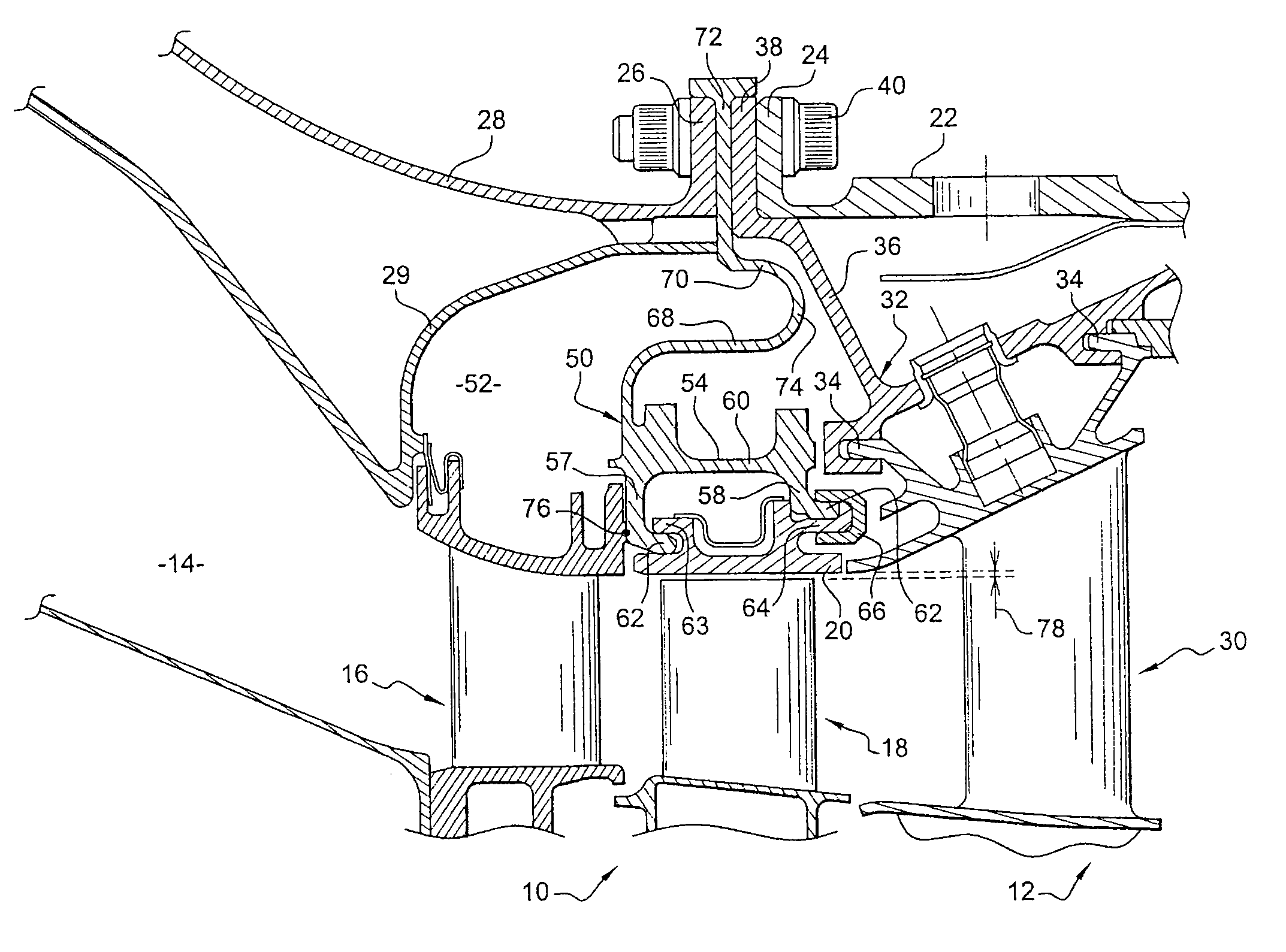
[0025]FIG. 1 represents schematically a portion of a turbomachine such as an aircraft turbojet or turboprop comprising a turbine arranged downstream of a combustion chamber 14, this turbine comprising several stages: an upstream stage, or high-pressure stage 10 and downstream stages or low-pressure stages 12.

[0026]The high-pressure stage 10 comprises an upstream guide vane element 16 formed of an annular array of fixed stator blades, and an impeller 18 mounted downstream of the upstream guide vane element 16 and rotating in a substantially cylindrical shroud formed by ring sectors 20 placed circumferentially end-to-end and suspended from a turbine casing 22.

[0027]Each low-pressure stage 12 also comprises an upstream guide vane element and an impeller of the aforementioned type, only the upstream guide vane element 30 of the first low-pressure stage being visible in FIG. 1. This upstream guide vane element 30 is attached to the turbine casing 22 by means of an annular supporting part...


PUM


Abstract

A turbine stage in a turbomachine including ring sectors arranged about a turbine impeller, and an annular support supporting the ring sectors and attached to a turbine casing is disclosed. The annular support is able to be deformed elastically in the radial direction to cushion at least a portion of the deformations of the turbine casing in operation.

Description

[0001]The present invention relates to a turbine stage in a turbomachine such as in particular an aircraft turbojet or turboprop.BACKGROUND OF THE INVENTION[0002]A turbomachine comprises several turbine stages each comprising an upstream guide vane element formed of an annular array of fixed stator blades and an impeller mounted rotatably downstream of the upstream guide vane element in a cylindrical or frustoconical shroud formed by ring sectors placed circumferentially end-to-end. The first of these stages is a high-pressure stage and the other stages situated downstream are low-pressure stages.[0003]It is important that the radial clearances between the impellers and the corresponding ring sectors be optimized in order to enhance the performance of the turbomachine and to prevent any friction of the blade ends on the ring sectors, which would result in these ends wearing and in the performance of the turbomachine deteriorating at all operating speeds.[0004]The ring sectors that s...

Claims


Application Information

Patent Timeline
Patent Type & Authority Patents(United States)
IPC IPC(8): F01D9/04
CPCF01D9/04F01D11/12F01D25/246F05D2240/11
Inventor DAKOWSKI, MATHIEUDORIN, CLAIREGENDRAUD, ALAIN DOMINIQUEPHILIPPOT, VINCENT
Owner SN DETUDE & DE CONSTR DE MOTEURS DAVIATION S N E C M A
Why Eureka
Try Eureka