Pulverized coal injection lance

a technology of injection lance and pulverized coal, which is applied in the direction of manufacturing converters, furnaces, combustion types, etc., can solve the problems of reducing the burning efficiency, so as to facilitate the ignition of flames, improve the stability of the flame and also the burning efficiency, and reduce the risk of burning out

Active Publication Date: 2010-01-07
PAUL WURTH SA
View PDF3 Cites 7 Cited by
  • Summary
  • Abstract
  • Description
  • Claims
  • Application Information

AI Technical Summary

Benefits of technology

[0010]In contrast to prior art lances where the pulverized coal mixes with the combustive gas after passing the tip of the lance, the discontinuity of the separation wall within the lance allows for the mixing of the pulverized coal and the combustive gas to start within the lance. It has been found that this facilitates flame ignition and improves the stability of the flame and also the burning efficiency. Indeed, with the mixing taking place inside the lance, near the front end thereof, the burning of the flame is maintained and is less prone to going out due to outside influences, such as fluid movement outside the lance. The mixing of the pulverized coal and the combustive gas inside the lance also facilitates the ignition of the flame; self-ignition of the flame is also improved.
[0011]The present arrangement, with the outer pipe and the inner pipe having substantially the same length and the inner pipe comprising at least one lateral opening near the front end of the lance, allows an improved control of the mixing of the pulverized coal and the combustive gas inside the lance. The partial mixing of the pulverized coal and the combustive gas allows an improved control over the temperature, thereby preventing burning of the “nose” of the lance. Furthermore, the inner pipe has a substantially constant diameter in and upstream of the mixing.

Problems solved by technology

If the spiral angle is too deep, the oxygen is directed away from the pulverized coal and the burning efficiency is decreased.
Although the above systems may, in certain conditions, be suitable for improving the burning efficiency, this effect is not guaranteed and there remains a risk that the flame is not maintained.
Furthermore, the modification of the lance, either by providing a flow swirler or by providing a plurality of dimples, may prove to be rather costly.

Method used


Image

  • Pulverized coal injection lance
  • Pulverized coal injection lance

Examples


first embodiment

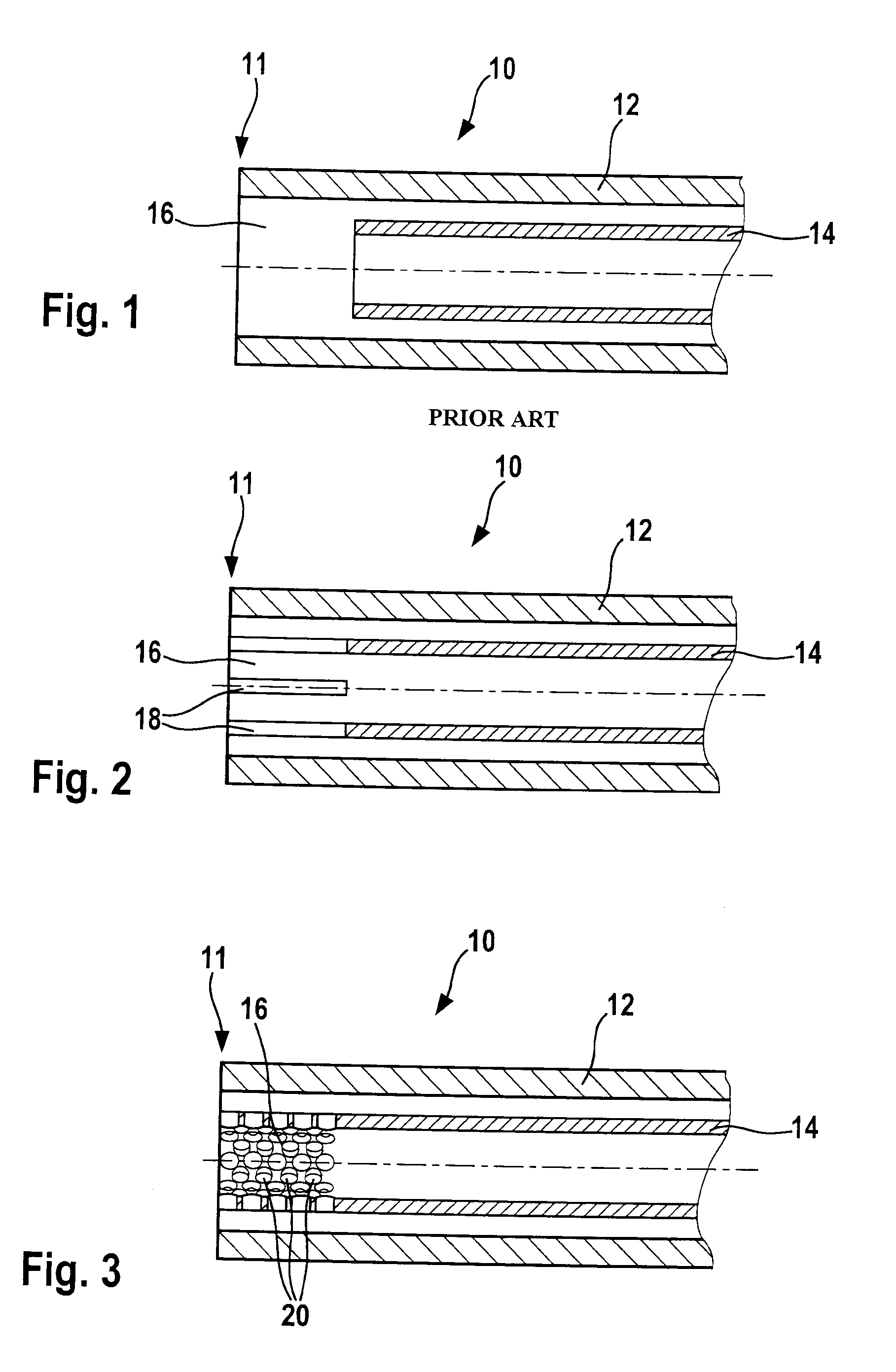
[0024]According to the invention, as illustrated in FIG. 2, the inner pipe 14 and the outer pipe 12 have substantially the same length and the discontinuity in the separation wall is formed by a series of four slits 18 arranged in the inner pipe 14. Due to the slits 18, the pulverized coal and the combustive gas are allowed to mix in the mixing region 16. The slits 18 in the illustrated embodiment are parallel to each other and to the axis of the inner pipe 12 and they extend over the whole length of the mixing region 16. It should be noted, however, that the slits 18 may also be arranged at an angle with respect to the axis of the inner pipe 12 or extend over only part of the length of the mixing region 16. Indeed, the degree of mixing in the mixing region 16 can be varied by choosing an appropriate number, orientation or size of slits 18.

second embodiment

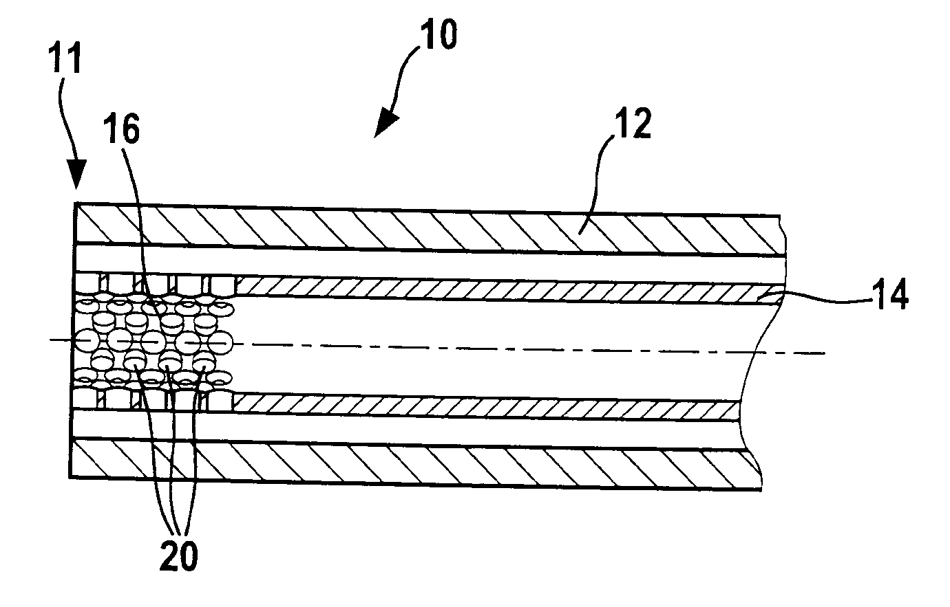
[0025]According to the invention, as illustrated in FIG. 3, the inner pipe 14 and the outer pipe 12 have substantially the same length and the discontinuity in the separation wall is formed by a plurality of boreholes 20 arranged in the inner pipe 14. Due to the boreholes 20, the pulverized coal and the combustive gas are allowed to mix in the mixing region 16. The boreholes 20 in the illustrated embodiment are arranged in zigzag layout and they extend over the whole length of the mixing region 16. It should be noted, however, that the boreholes 20 may also be arranged according to another layout or extend over only part of the length of the mixing region 16. Indeed, the degree of mixing in the mixing region 16 can be varied by choosing an appropriate number, orientation or size of boreholes 20.


PUM

PropertyMeasurementUnit
widthaaaaaaaaaa
widthaaaaaaaaaa
diameteraaaaaaaaaa

Abstract

The present invention proposes a pulverized coal injection lance (10) for feeding pulverized coal from a rear end of the lance (10) to a front end (11) of the lance (10). The lance (10) comprises an outer pipe (12) for conveying combustive gas, and an inner pipe (14), coaxially arranged within the outer pipe (12), for conveying pulverized coal. The inner pipe (14) forms a separation wall for separating the pulverized coal from the combustive gas. The separation wall is at least partially discontinued in a region near the front end (11) of the lance (10), thereby forming a mixing region (16) within the pulverized coal injection lance (10). According to an important aspect of the invention, the outer pipe (12) and the inner pipe (14) have substantially the same length and wherein the inner pipe (14) comprises at least one lateral opening (18, 20) for allowing pulverized coal and combustive gas to come into contact within the pulverized coal injection lance (10) near the front end (11).

Description

TECHNICAL FIELD OF THE INVENTION[0001]The present invention relates to a pulverized coal injection lance, in particular for feeding pulverized coal into a tuyere of a blast furnace.BRIEF SUMMARY OF RELATED ART[0002]Pulverized coal injection lances are generally used to inject pulverised coal as a substitute to coke into a blast furnace. The pulverized coal is conveyed pneumatically through the lance and bums at the tip of the lance. The burning of the pulverized coal is aided by the supply of oxygen to the tip of the lance.[0003]The so-called Oxycoal technology comprises an injection lance having an inner pipe for conveying the pulverized coal and an outer pipe, surrounding the inner pipe, for conveying the oxygen. At the tip of the lance, the oxygen meets the pulverized coal to improve the burning of the pulverized coal.[0004]EP 1 060 272 describes that the burning of the pulverized coal can be improved and the flame maintained by providing a flow swirler between the coaxial pipes ...

Claims


Application Information

Patent Timeline
Patent Type & Authority Applications(United States)
IPC IPC(8): C21B7/16
CPCC21B5/003C21B7/163C21C5/5217Y02E20/344F23L7/007F27D1/18Y02E20/322F23D1/00Y02E20/32Y02E20/34Y02P10/32Y02P10/20C21B7/16C21B5/00
Inventor KROEMMER, YVANGOEDERT, PAULSTAMATAKIS, GEORGES
Owner PAUL WURTH SA
Why Eureka
Try Eureka