
Attachable mailer

a mailer and attachment technology, applied in the field of mailers, can solve the problems of limiting the size of the envelope, time-consuming assembly, and the inability of the sender to meet the requirements of the envelope, and achieve the effect of simple and time-efficien

Inactive Publication Date: 2002-09-19
SANDERS RAYMOND W +2
View PDF0 Cites 2 Cited by
  • Summary
  • Abstract
  • Description
  • Claims
  • Application Information

AI Technical Summary

Benefits of technology

[0013] The various embodiments of the invention are capable of being assembled and / or affixed to an object to be mailed in a simple and time-efficient manner. The mailer embodiments of the invention are also capable of affixation to any object to be mailed regardless of the size and type of the object to be mailed. Although the mailers are depicted according to the one-size-fits all paradigm, the mailers may also be designed to fit a specific size / type of object if such is required.

Problems solved by technology

These mailers, however, present two significant drawbacks.
First, the sender is limited to the size of the envelope formed by the assembled mailer.
Second, these constructions are typically complex in nature and time-consuming to assemble.
This results in either a substantial cost in human resources to assemble and stuff such envelope mailers or a substantial investment in machinery to automate this process.
This cost is compounded when the sender wishes to use a special form of mailing, such as certified mail, due to the additional fields which postal service forms require.
Manual preparation of such special mail is particularly labor-intensive when large quantities of such individualized mail, e.g., mass mailings, are generated.
Most prior art certified mailers employ a complicated construction in which various sections of the mailer seal to form an envelope.
These prior art mailers, such as shown in U.S. Pat. No. 5,901,903, however, lack flexibility in dealing with different sized contents or packages because the mailer comprises two layers which are joined together to form an envelope that is capable of receiving contents of limited sizes.
Prior-art envelope mailers do not satisfy this need for multi-purpose mailers.
This system is cumbersome due to the multitude of labels and time-consuming process of peeling backings off of each label and then affixing the individual labels to the object to be mailed.

Method used


Image

  • Attachable mailer
  • Attachable mailer
  • Attachable mailer

Examples


Embodiment Construction

[0028] A mailer, as used in this application, shall mean a sheet configured to be capable of being affixed to an object to be mailed to a recipient, such as an envelope, magazine, package, etc.

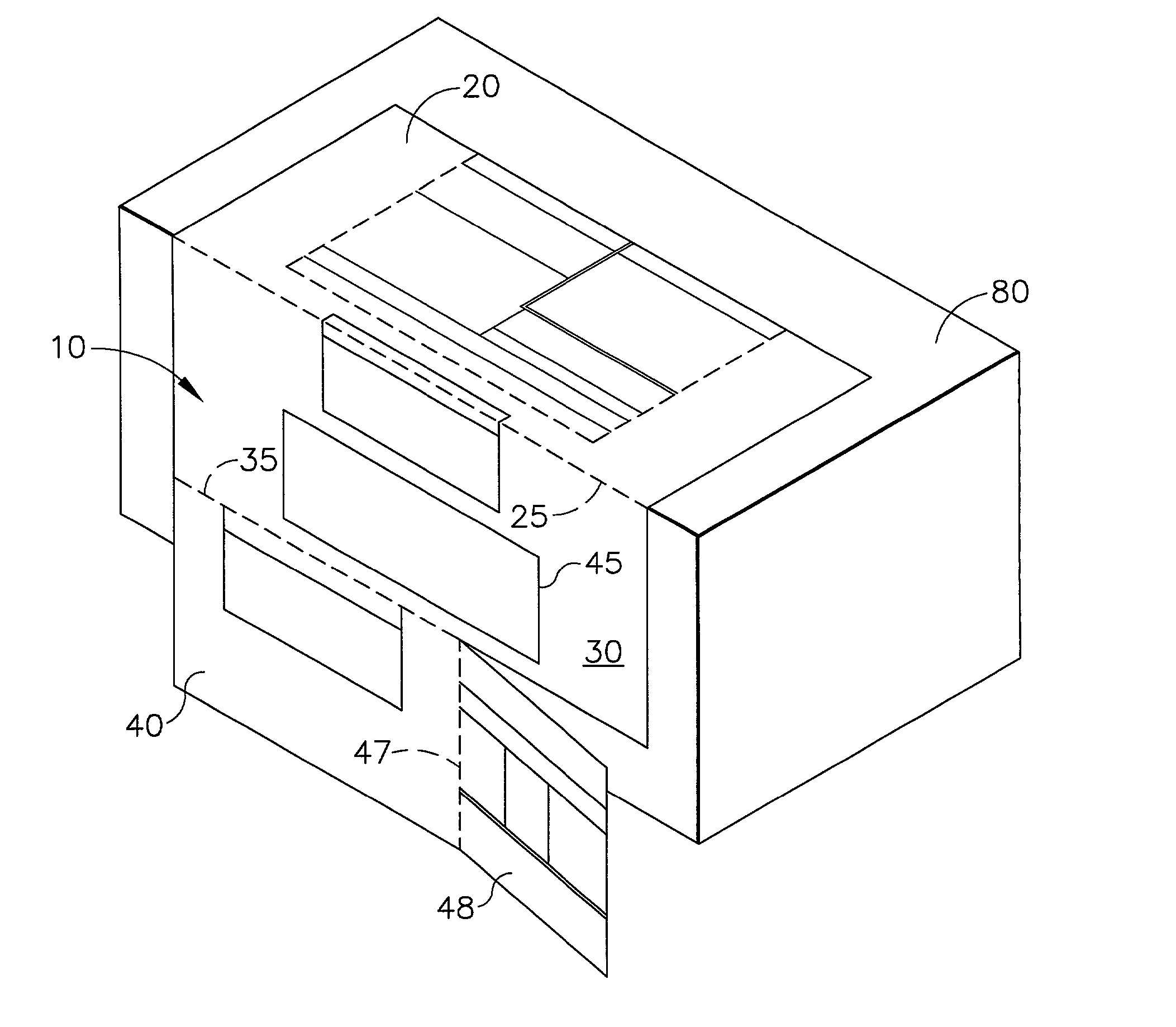
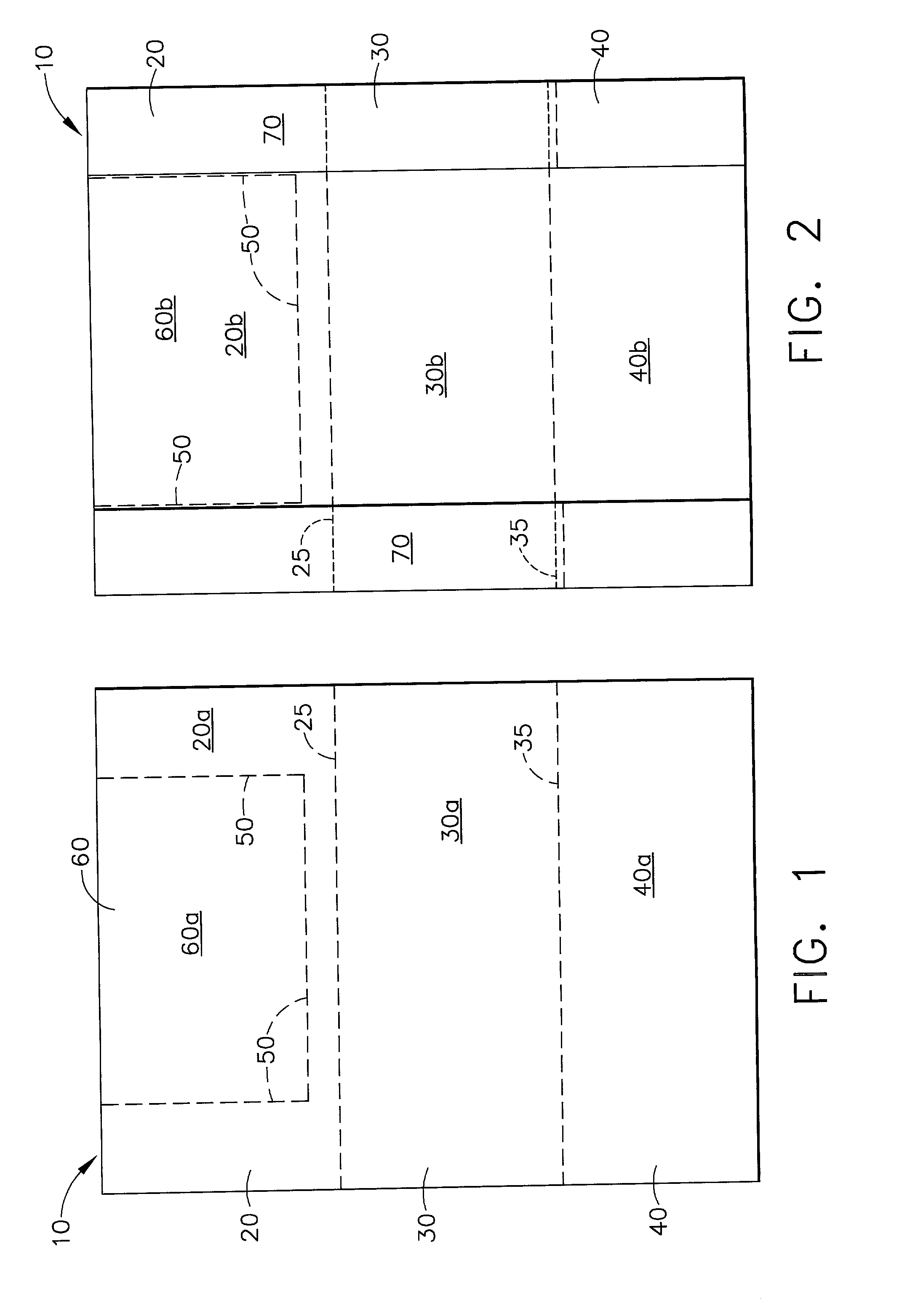
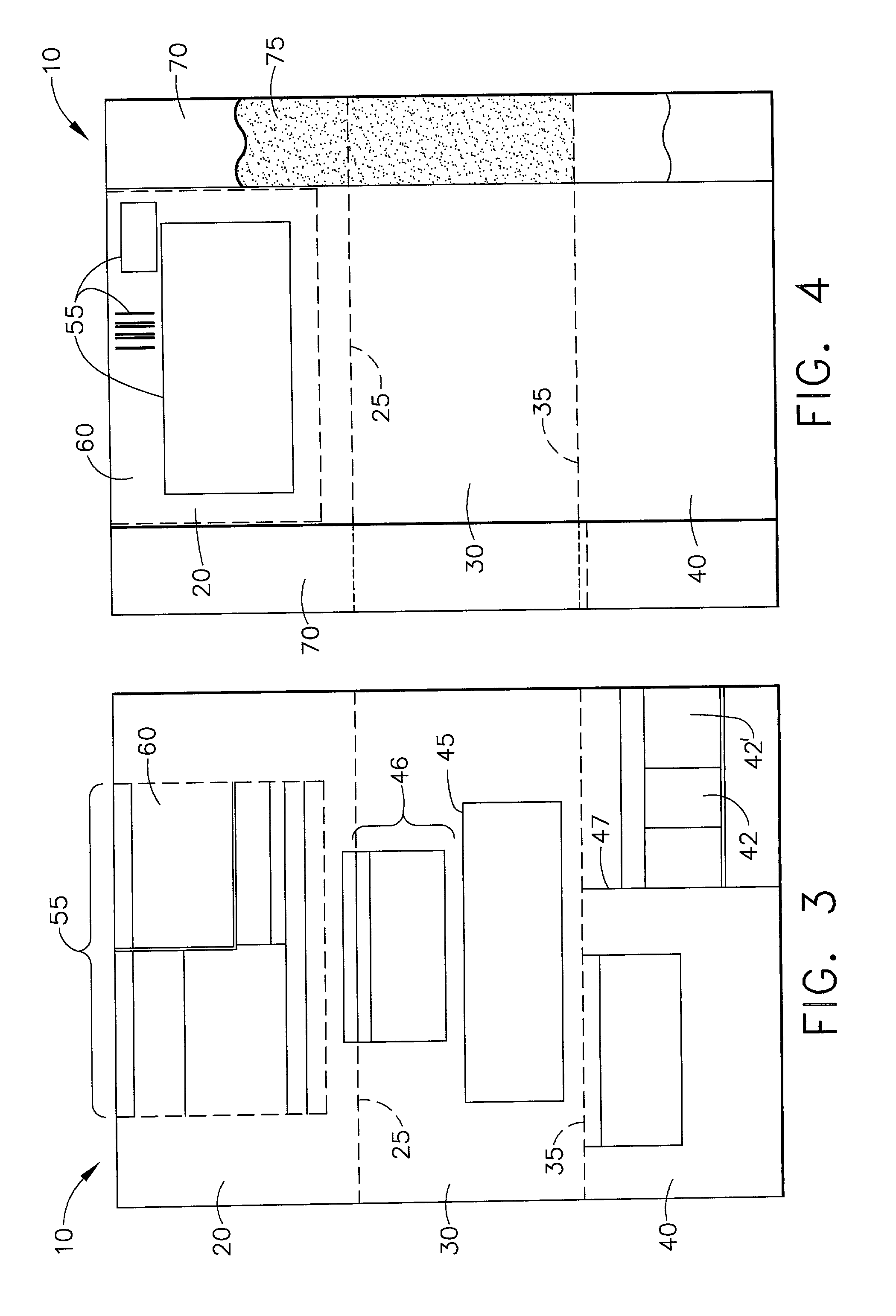
[0029] Referring to FIGS. 1 and 2, an embodiment of the mailer (10) is shown which has double sided indicia. The mailer (10) comprises a single sheet comprising a one piece integral structure. As illustrated in FIGS. 1 and 2, the mailer (10) includes integrally formed first (top) panel (20), second (middle) (30) panel, and third (bottom) panel (40). Each panel has respective outside surfaces (20a, 30a, 40a) and inside surfaces (20b, 30b, 40b) surfaces. (As used herein, the outside surface is the surface which is visible to one handling the object to be mailed after the mailer has been affixed to that object.) The panels are defined by respective, transversely extending foldlines (25, 35).

[0030] Foldlines (25, 35) may be achieved in any manner including by using tools well known in the art such...


PUM


Abstract

A mailer, for attachment to an object to be mailed, has an integrally constructed single sheet mailer having a detachable form and a recipient address label. The detachable form may be used with certified mailing as a return receipt post card.

Description

TECHNICAL FIELD[0001] The invention relates to mailers, and more particularly to a single-sheet mailer capable of being attached to a variety of different size objects including envelopes, magazines, and boxes. The mailer is also capable of being pre-printed or custom-printed in either one or two passes through a printer.BACKGROUND OF THE INVENTION[0002] Continuous form webs have previously been separated into discrete forms and folded to form mailers with integral envelopes in which a sender may insert the contents they desire to mail. Such mailers have also included detachable postcards to be used as return receipts or mail receipts. These mailers, however, present two significant drawbacks. First, the sender is limited to the size of the envelope formed by the assembled mailer. Second, these constructions are typically complex in nature and time-consuming to assemble. This results in either a substantial cost in human resources to assemble and stuff such envelope mailers or a sub...

Claims


Application Information

Patent Timeline
Patent Type & Authority Applications(United States)
IPC IPC(8): B42D15/00B42D15/08
CPCB42D15/006B42D15/08
Inventor SANDERS, RAYMOND W.FERRARELLI, JOSEPH R.SANDERS, THOMAS C.
Owner SANDERS RAYMOND W
Learn More