
Device and method for patterning a surface of a polymer layer

a polymer layer and surface technology, applied in nanoinformatics, instruments, record information storage, etc., can solve the problems of limiting data rates on the order of khz rather than mhz, tip and/or media wear may be typically expected to occur, and the magnitude of an associated electrical stray field is increased by an order, so as to achieve simple and time-efficient effects

Inactive Publication Date: 2010-03-11
IBM CORP
View PDF4 Cites 1 Cited by
  • Summary
  • Abstract
  • Description
  • Claims
  • Application Information

AI Technical Summary

Benefits of technology

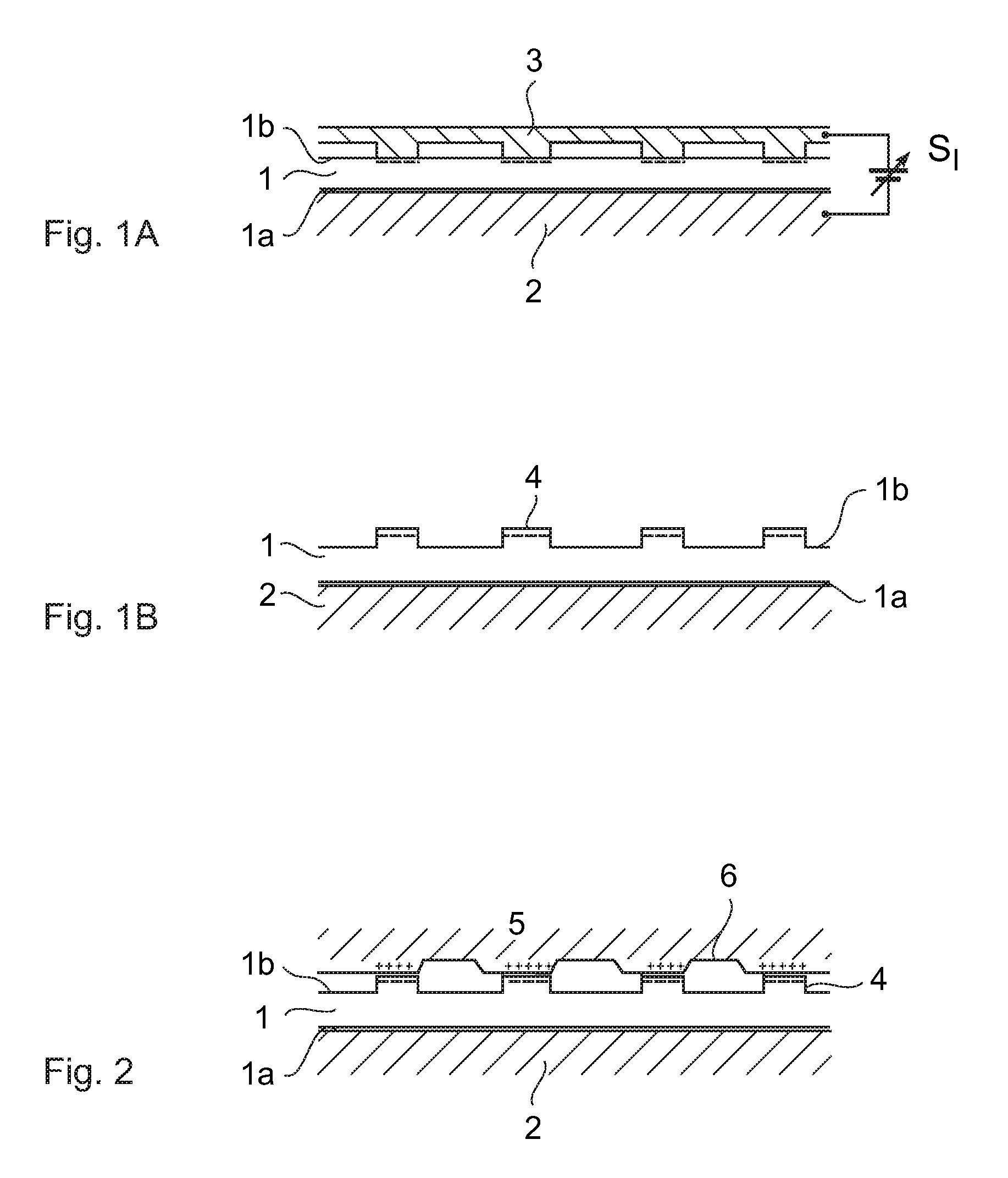
[0016]Preferably, the device is operable to apply a second electrical potential to the at least one electrode, which interacts with the second surface of the polymer layer in the region where the protrusion has been formed, the second electrical potential having an opposite polarity to the first electrical potential. By the selection of an appropriate polarity and magnitude for the second electrical potential, a protrusion formed on the second surface of the polymer layer may be enhanced, reduced or the second surface of the polymer layer may even be returned to an uncharged, neutral state. Furthermore, such reversible operation allows modification of the topographic landscape of the second surface of the polymer layer to be done sequentially.
[0017]Preferably, the device is operable to apply heat, irradiation or a combination thereof to the polymer layer. Protrusions formed on the second surface of the polymer layer may be globally removed by applying a suitable form of energy such as, for example, the application of heat, irradiating with ultra-violet radiation and / or charged particles, or a combination thereof. In this way, the second surface of the polymer layer may be returned to a state where new protrusions may subsequently be written thereon in a simple and time-efficient manner. In this case, it is preferable that the polymer layer is heated to a temperature of between 100° C. to 200° C. Since the decay rate of the injected charge typically increases by one order of magnitude per 20° C. change in temperature, charge could be neutralized in a timescale of seconds by heating the polymer layer to temperatures between 100° C. to 200° C. in an embodiment of the present invention.

Problems solved by technology

Due to the mechanical stress that is used for writing indentation marks in the polymer layer, tip and / or media wear may be typically expected to occur.
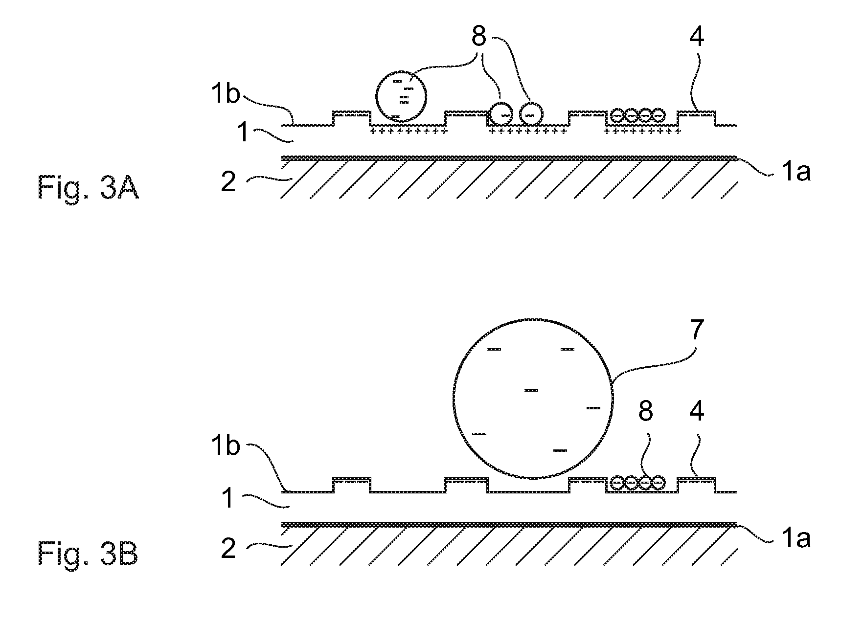
Other issues that may need to be considered in the detection of the localized trapped charges are: (1) the aforementioned electrical stray field is long range by nature and so may result in the “smearing out” of a bit location; (2) a localized trapped charge is typically screened by polar contaminants, for example, water molecules, thereby reducing the magnitude of an associated electrical stray field by an order of magnitude within a short time, typically within 24 hours, of charge injection, and (3) the magnitude of the aforementioned interaction force may limit data rates on the order of kHz rather than MHz.
Furthermore, the detection of such sub-nanometre dimensioned features using known detectors may typically be done with a limited data rate in the kHz range.
It is a challenge to produce asperities such as, for example, protrusions, on the surface of a polymer layer using these techniques.

Method used


Image

  • Device and method for patterning a surface of a polymer layer
  • Device and method for patterning a surface of a polymer layer
  • Device and method for patterning a surface of a polymer layer

Examples


Embodiment Construction

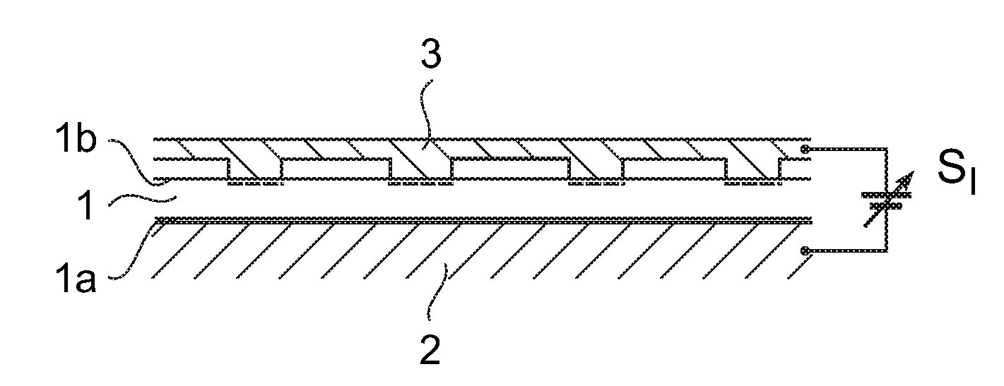
[0033]FIGS. 1a and 1b schematically illustrate the principle of an embodiment of the present invention.

[0034]A first surface 1a of a polymer layer 1 is provided on a substrate 2. It may be provided directly on the substrate 2 or on a spacer layer which may, for example, be silicon oxide. The polymer layer 1 comprises polystyrene-r-benzocyclobutene 30% random copolymer, PS-30%-BCB. The present invention is, however, not limited to PS-30%-BCB and any other polymer that is non-conducting and, optionally, cross-linkable may be used. The substrate 2 comprises silicon with an n-type doping concentration of, for example, 1016 cm−3. The substrate 2 is, of course, not limited to the use of silicon and any other material having an appropriate electrical conductance may be used.

[0035]A second surface 1b of the polymer layer 1 is provided so as to interact with at least one electrode 3 either by being in contact with or in close proximity thereto, i.e. with there being a separation between the ...


PUM

PropertyMeasurementUnit
distanceaaaaaaaaaa
temperatureaaaaaaaaaa
diameteraaaaaaaaaa

Abstract

The present invention relates to a device for forming topographic features on a surface of a polymer layer comprising: a polymer layer (1); a substrate (2) comprising a conductor, a first surface (1a) of the polymer layer (1) being provided on the substrate (2); and at least one electrode (3) which, when the device is in use, interacts with a second surface (1b) of the polymer layer (1), wherein, when in use, the device is operable to apply a first electrical potential (P1) to the at least one electrode (3) relative to the substrate (2), thereby to cause a protrusion (4) to be formed on the second surface (1b) of the polymer layer (1).

Description

FIELD OF THE INVENTION[0001]The present invention relates to a device and a method for patterning a surface of a polymer layer. In particular, the present invention relates to a device and a method for forming topographic features and, more specifically, protrusions, on a surface of a polymer layer.BACKGROUND OF THE INVENTION[0002]A probe-type data storage device based on the atomic force microscope (AFM) is disclosed in “The millipede—more than 1,000 tips for future AFM data storage” by P. Vettiger et al., IBM Journal Research Development, Vol. 44, No. 3, March 2000. The storage device has a read and write function based on a mechanical x-, y-scanning of a storage medium with an array of probes each having a tip. The probes operate in parallel with each probe scanning, during operation, an associated field of the storage medium. The storage medium comprises a polymethylmethacrylate (PMMA) layer. The tips, which each have a diameter of between 5 nm to 40 nm, are moved across the sur...

Claims


Application Information

Patent Timeline
Patent Type & Authority Applications(United States)
IPC IPC(8): C25D1/00
CPCB82Y10/00G11B11/007G11B9/1472G11B9/14
Inventor DUERIG, URS T.GOTSMANN, BERND W.KNOLL, ARMIN W.
Owner IBM CORP
Learn More