Locking hinge

a hinge and hinge body technology, applied in the field of locking hinges, can solve the problems of not being easily adaptable to paintball guns and shoulder rests

Inactive Publication Date: 2003-03-20
BLACKPOINT ENG
View PDF0 Cites 16 Cited by
  • Summary
  • Abstract
  • Description
  • Claims
  • Application Information

AI Technical Summary

Problems solved by technology

Such shoulder rests are not readily adaptable for use on paintball guns.
Such a paintball gun shoulder rest prese...

Method used


Image

  • Locking hinge
  • Locking hinge
  • Locking hinge

Examples


Embodiment Construction

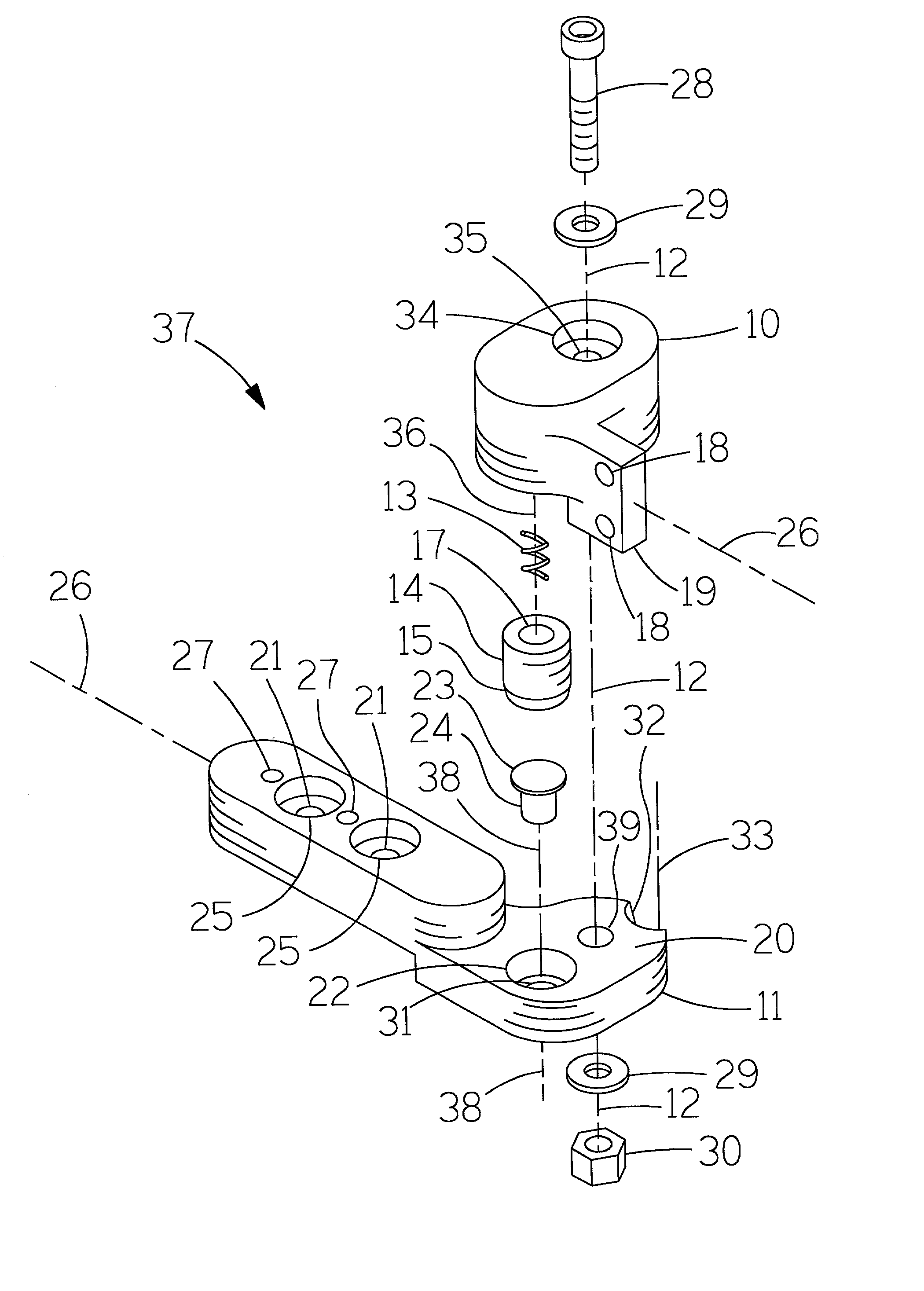
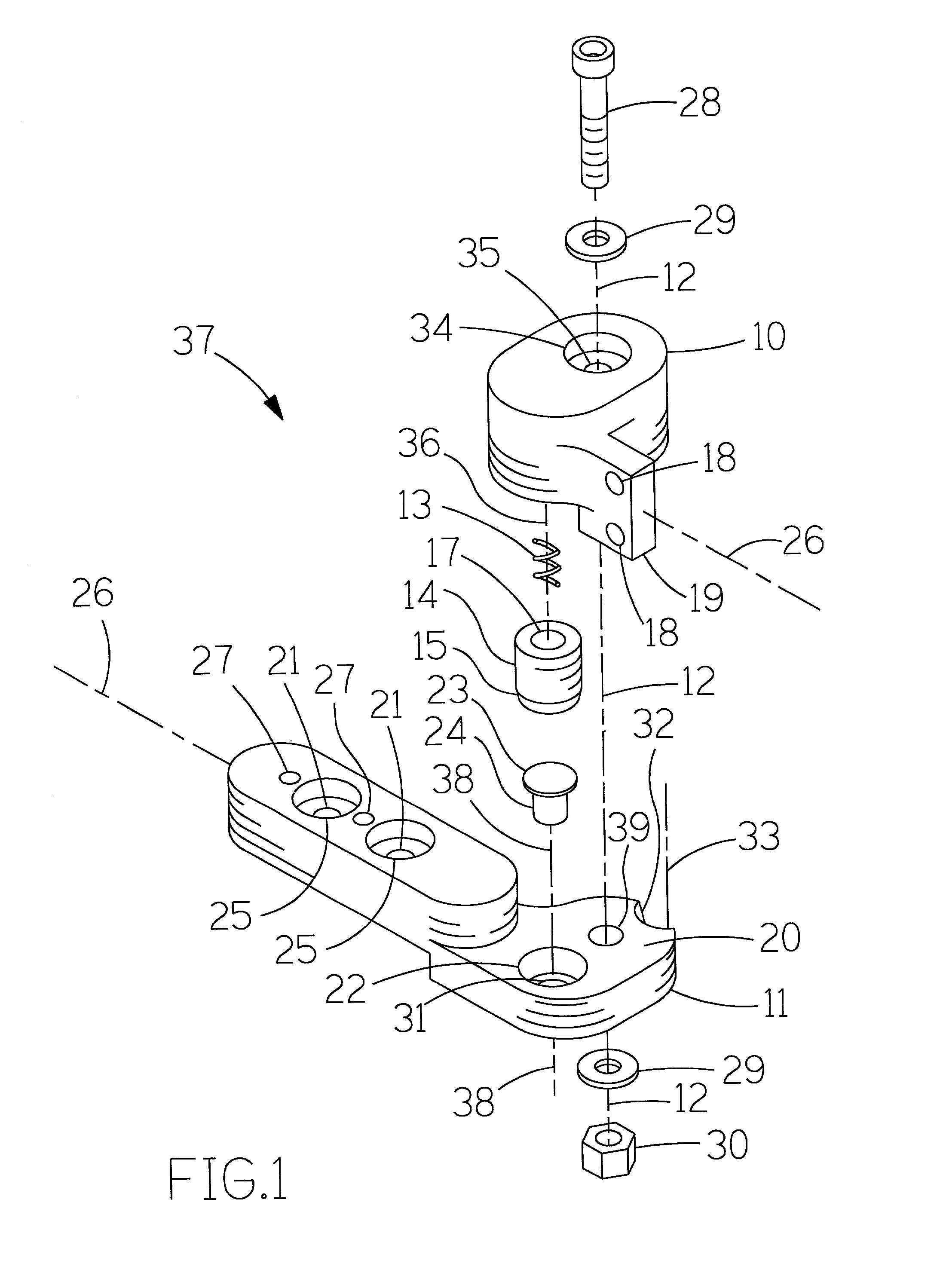
[0018] Referring now to the drawings, and more particularly FIGS. 1-3, there is shown a locking hinge 37. Generally, a locking hinge 37 includes a hinge joint axis 12, a first hinge plate 10, a second hinge plate 11, a spring 13, a locking cylinder 14 and a push button 24.

[0019] Shown in FIGS. 4, 5 and 6, a first hinge plate 10 has a receiving counter bore 16 which contains a spring 13 and guides locking cylinder 14. One end of spring 13 contacts the bottom of counter bore 16. The other end of spring 13 contacts locking cylinder 14 through spring guide hole 17. Counter bore 16 allows locking cylinder 14 free movement along the axis of the locking mechanism 36. First hinge plate 10 has a symmetry axis 26. First hinge mounting holes 18 are equally spaced about the symmetry axis 26.

[0020] As seen in FIGS. 1, 5 and 6, second hinge plate 11 has receiving hole 31 which push button 24 is inserted. Push button 24 stops at the bottom of tapered circular cavity 22 because of flange 23. Tapere...


PUM


Abstract

A locking hinge especially used in a folding shoulder rest for paintball guns. The locking hinge comprises a first hinge plate and a second hinge plate in relative rotation. The first hinge plate has a hinge joint axis, a plurality of symmetric mounting holes, and a counter bore for receiving the locking mechanism. The counter bore in the first hinge plate contains a spring and a locking cylinder. The locking cylinder has a taper on the end directed toward the second hinge plate. The second hinge plate has a relative hinge joint axis, a plurality of tapered circular cavities or notches, and a means for symmetric mounting. The locking mechanism sufficiently aligns with the tapered circular cavities or notches at plurality of predetermined positions thereby preventing rotation of the hinge plates. A minor misalignment between the locking mechanism and tapered circular cavities further provide rigid locking of the hinge plates.

Description

[0001] This invention relates to locking hinges especially for use in a folding shoulder rest for paintball guns.BACKGROUND--DESCRIPTION OF RELATED ART[0002] Locking hinges presently exist in folding shoulder rests built for real guns. Such shoulder rests are not readily adaptable for use on paintball guns. Paintball gun shoulder rests that exist are only telescopic for arm length. Such a paintball gun shoulder rest presents a problem in that the shoulder rest does not fold, allowing for compact storage or compact use of a paintball gun.[0003] The present invention relates to a locking hinge having two rotatable plates. A first hinge plate contains a locking mechanism, which is a spring and a locking cylinder. The locking cylinder has a tapered end directed toward the second hinge plate. A second hinge plate incorporates a tapered circular cavity or notch, which receives the tapered end of the locking cylinder. There is a misalignment of the axis of the locking mechanism and the axi...

Claims


Application Information

Patent Timeline
IPC IPC(8): F41C23/04
CPCF41C23/04Y10T16/558Y10T16/54025
Inventor WYGANT, STEVEN JOHN
Owner BLACKPOINT ENG
Why Eureka
Try Eureka