

Multi-focal intraocular lens, and methods for making and using same
a multi-focal, intraocular lens technology, applied in intraocular lenses, medical science, prosthesis, etc., can solve the problems of reducing the ability to focus for the same muscle action, affecting the optical focusing system of the eye, and the efficiency of the ciliary body-zonules-lens complex becoming less efficient at accommodating the focus of these rays, so as to achieve the effect of restoring the focus mechanism and not affecting the field of vision
- Summary
- Abstract
- Description
- Claims
- Application Information
AI Technical Summary
Benefits of technology
Problems solved by technology
Method used
Image

Examples
first embodiment
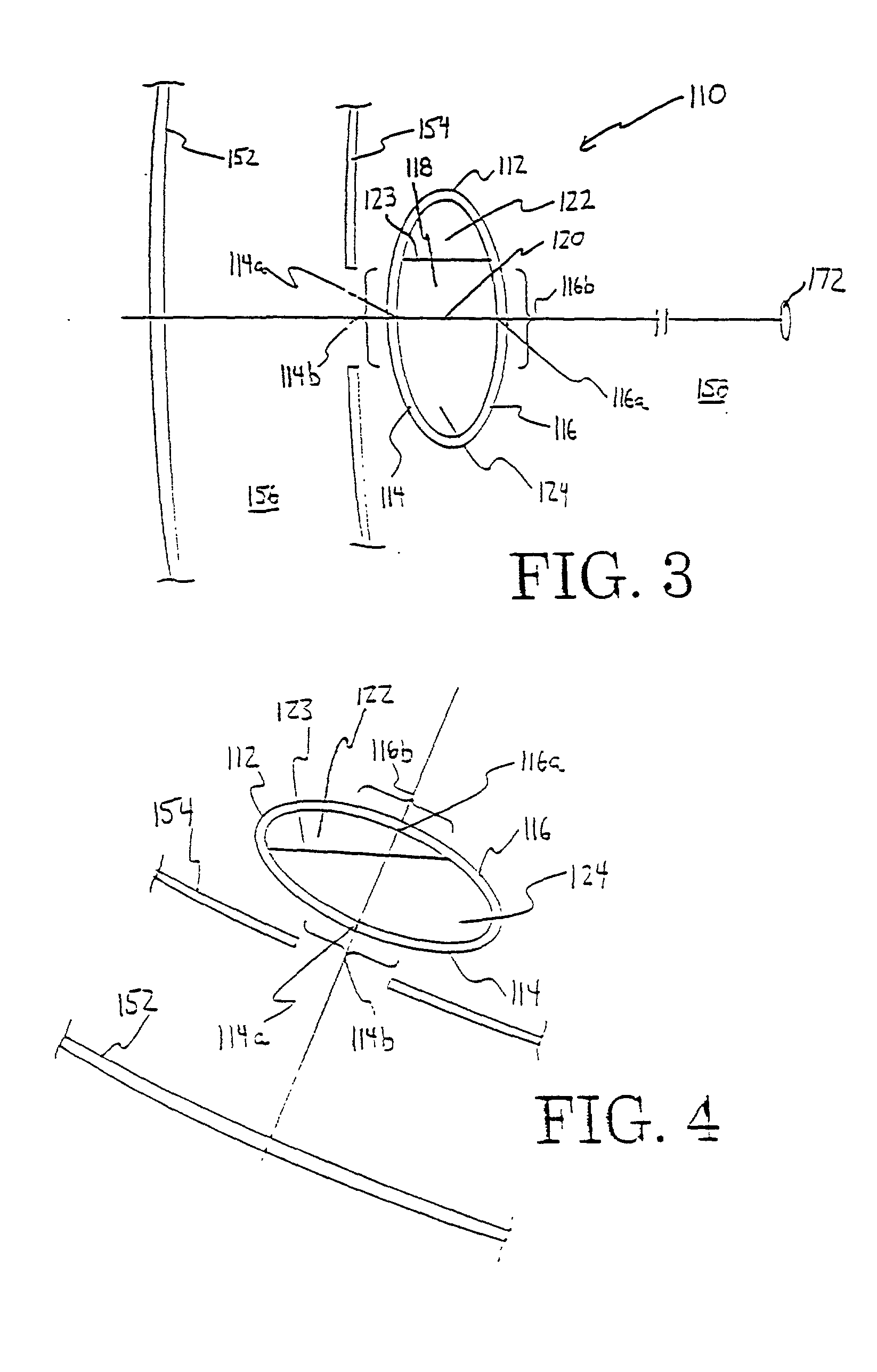
[0057] Because the fluids possess refractive indices, it is possible for one of the walls 114 and 116 to possess no curvature, i.e., to be planar or non-curved. Further, the radii of curvature of the anterior wall 114 and the posterior wall 116 may have the same or different absolute values from each other, depending upon the desired strength of the lens 110. It is also within the scope of the invention to use multiple anterior walls 114 and / or multiple posterior walls 116, and / or to have the anterior wall 114 and / or posterior wall 116 comprised of laminates. Further, the anterior wall 114 and / or posterior wall 116 may be implanted with a lens element or bi-refringent materials. Another possibility is to employ anterior and / or posterior walls with discrete refractive zones, especially concentric zones, such as in the case of Fresnel magnification. However, the optic body 112 of this first embodiment and other embodiments described herein is preferably, although not necessarily, free...
second embodiment
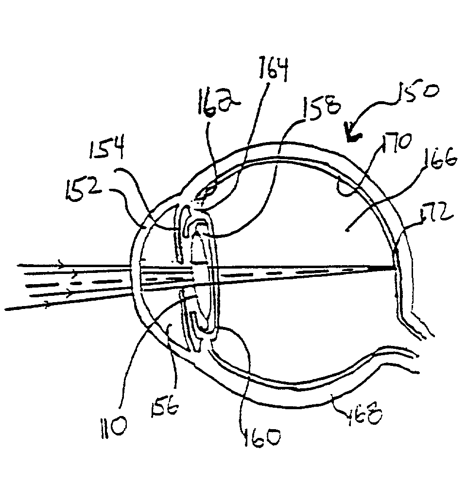
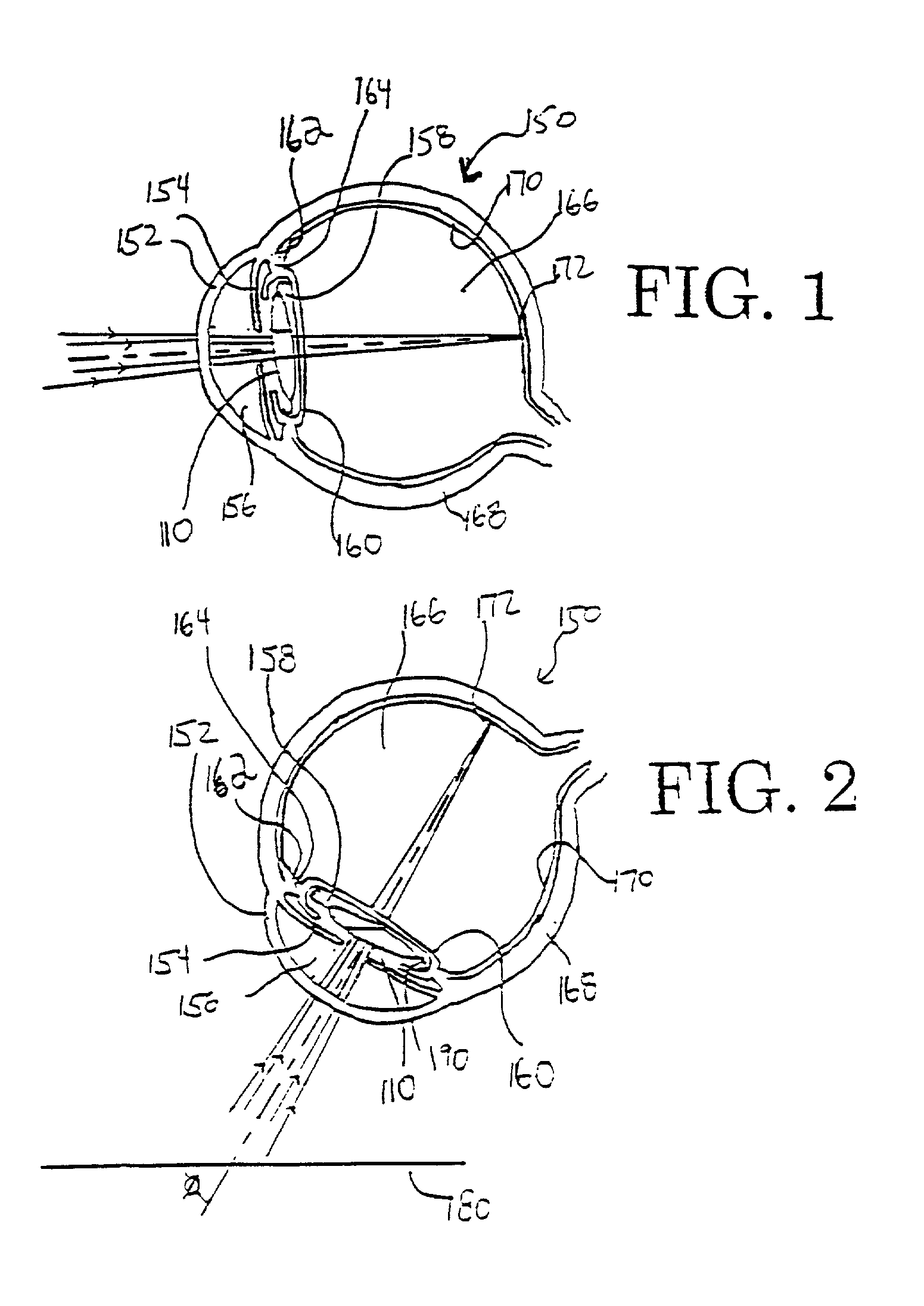
[0073] FIG. 5 shows the intraocular lens 210 of this invention positioned in the posterior chamber 258 of the eye gazing straight ahead at the pr. In this straight-ahead gaze, the optical axis 220 is parallel to the axis along the horizontal plane. The optically transmissive lower liquid 224 is present in a sufficient amount that orienting the optical axis 220 in a horizontal orientation positions the optical axis 220 through the upper fluid 222, and most of the anterior visual zone 214b and the posterior visual zone 216b are immersed in the upper fluid 222. Preferably, the upper fluid 222 is present in a sufficient amount that in the straight-ahead gaze at least 70 percent, and more preferably all, of the anterior and posterior visual zones 214b and 216b are immersed in the upper fluid 222. Thus, in straight-ahead gaze, light entering the IOL travels along the optical axis and is primarily refracted by the upper fluid 222. It is believed that any distortion caused by the presence o...
examples
[0101] All examples were modeled on the Zemax Version 10.0 optical design program, SE edition, from Focus Software, Inc.
[0102] The human eye was first modeled as a typical or schematic adult human emmetrope, as described in the Optical Society of America Handbook. Each of the models described below is for a posterior chamber IOL design. The following assumptions were made for the human eye for the purposes of the calculations. The model was assumed to have spherical surfaces only (whereas the real cornea and lens are actually aspherics). Each structure of the schematic human eye was assumed to be made of a material having a uniform or homogenous index (whereas in the real human eye, the index of refraction may vary somewhat through each structure of the eye). The model also assumed that the capsular bag walls were very thin and parallel, i.e., non-existent. The lens was assumed to have symmetric radius, i.e., spherical. The pr was assumed to be 10 meters. Three wavelengths with equa...
PUM
 Abstract
Description
Claims
Application Information