Portable sensory input device

a sensory input and portable technology, applied in the field of input devices, can solve the problems of high sensitiveness of input devices to variances in position and orientation, fragile input device components, and easy damage of input devices

Inactive Publication Date: 2003-07-17
CANESTA
View PDF10 Cites 97 Cited by
  • Summary
  • Abstract
  • Description
  • Claims
  • Application Information

AI Technical Summary

Problems solved by technology

The technology used to construct such a portable device often requires satisfaction of very difficult geometrical or mechanical constraints in order to ensure proper operation.
In addition, the various components of such input d

Method used


Image

  • Portable sensory input device
  • Portable sensory input device
  • Portable sensory input device

Examples


Embodiment Construction

[0036] The following description of system components and operation is merely exemplary of embodiments of the present invention. One skilled in the art will recognize that the various designs, implementations, and techniques described herein may be used alone or in any combination, and that many modifications and equivalent arrangements can be used. Accordingly, the following description is presented for purposes of illustration, and is not intended to limit the invention to the precise forms disclosed.

[0037] Overall Design

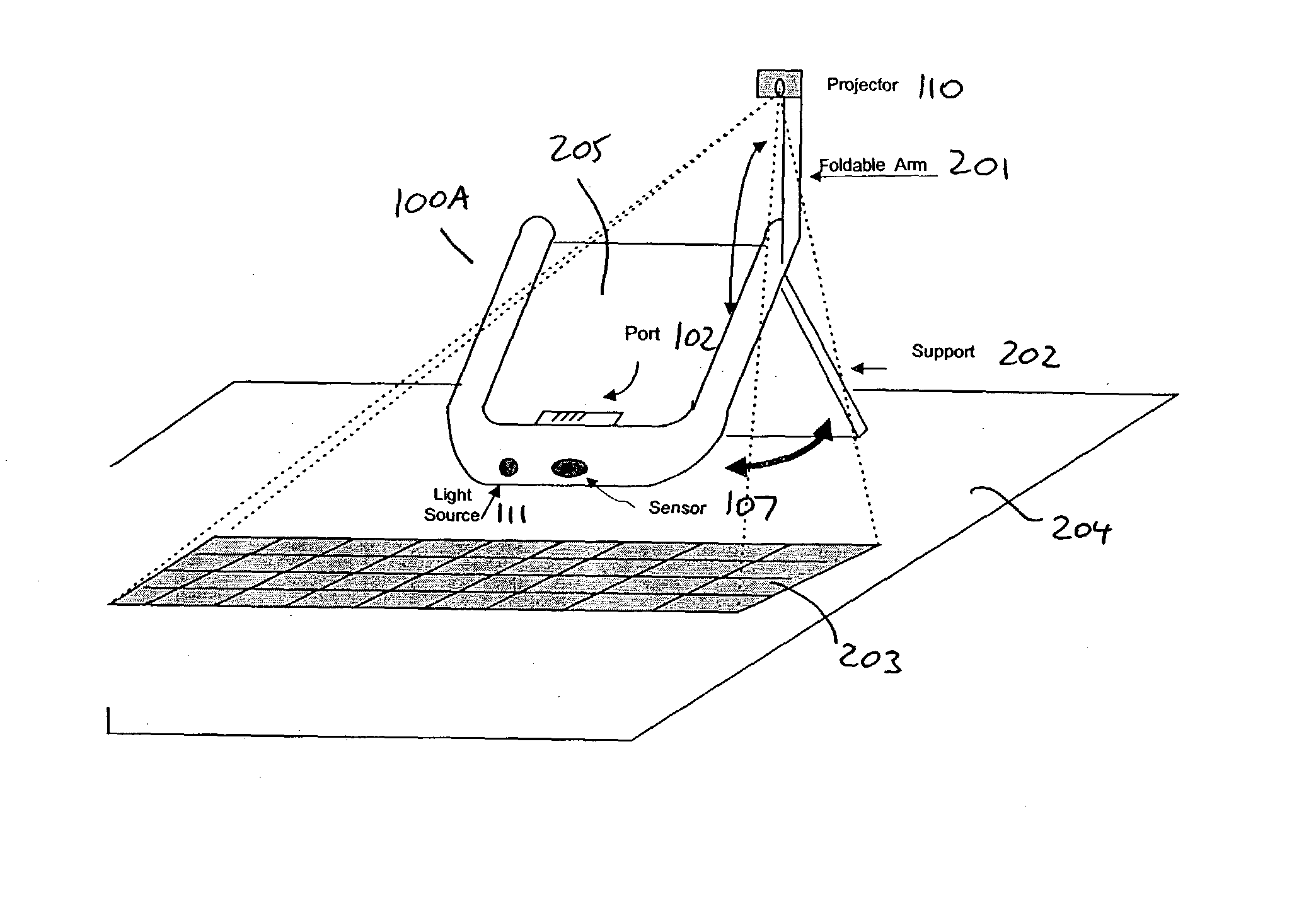
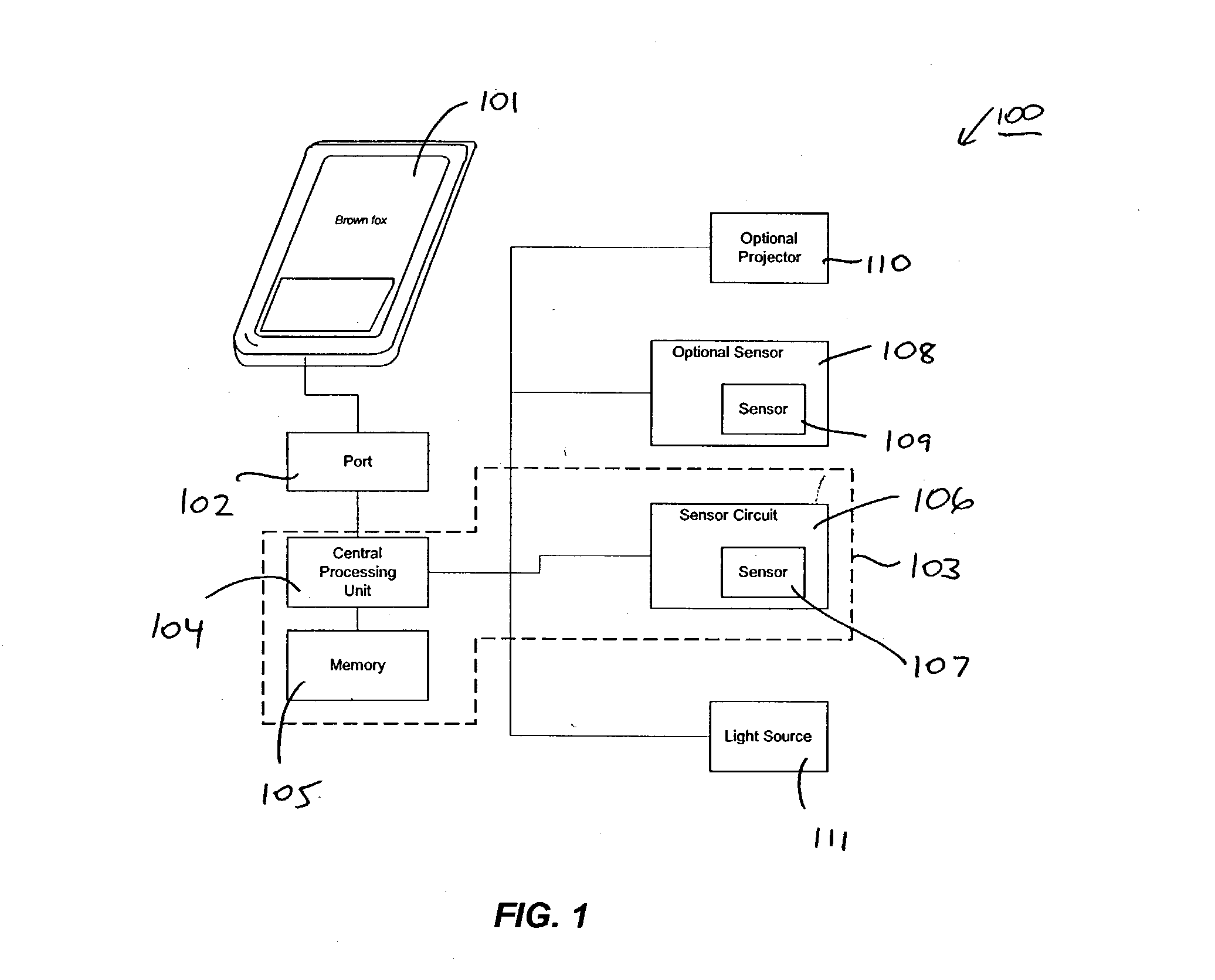
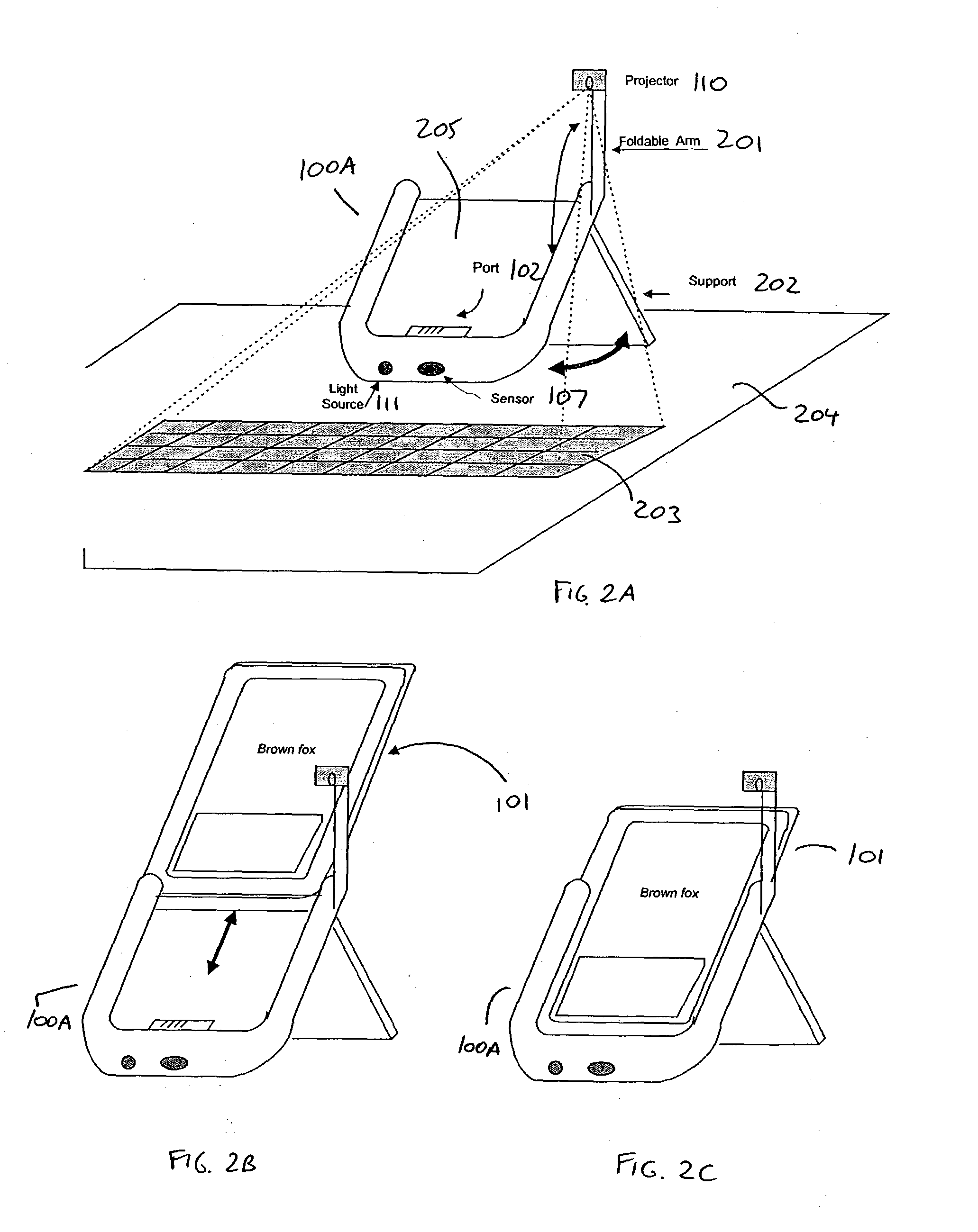
[0038] Referring now to FIG. 1, there is shown a block diagram of an exemplary portable input device 100 according to one embodiment of the present invention. In general, input device 100 operates to provide input to a host device 101, which may be a PDA, cell phone, or the like. Input device 100 can be enclosed in host device 101 or in a separate housing (not shown in FIG. 1). In one embodiment, the present invention provides mechanisms for implementing data inpu...


PUM


Abstract

An input device provides input to a portable electronic device. The device detects movement of a user's fingers on an inert work surface, and transmits signals representing the detected input to the electronic device. The input device can take any of several forms, including a cradle or protective cover that attaches to the electronic device, or a separate unit that transmits signals to the electronic device via a wired connection or wireless connection. In an embodiment, techniques are employed to properly position the input device despite user adjustment to the position of the electronic device. In an embodiment, further techniques are employed to maximize the stability of the input device and to protect its components from damage.

Description

[0001] This application claims priority from U.S. provisional patent application serial No. 60 / 339,234 for "Method and Apparatus for Stability and Alignment of a Portable Sensory Input Device," filed Dec. 7, 2001, the disclosure of which is incorporated herein by reference.[0002] The present application is a continuation-in-part of U.S. patent application Ser. No. 09 / 502,499 for "Method and Apparatus for Entering Data Using a Virtual Input Device," filed Feb. 1, 2000, the disclosure of which is incorporated herein by reference, and which in turn claims priority from U.S. Provisional Patent Application Serial No. 60 / 163,445 for "Method and Device for 3D Sensing of Input Commands to Electronic Devices," filed Nov. 4, 1999.[0003] The present application is a continuation-in-part of U.S. patent application Ser. No. 09 / 948,508 for "Quasi-Three-Dimensional Method and Apparatus To Detect and Localize Interaction of User-Object and Virtual Transfer Device," filed Sep. 7, 2001, the disclosur...

Claims


Application Information

Patent Timeline
IPC IPC(8): G01S3/808G01S5/18G01S5/22G01S17/06G06F1/16G06F3/00G06F3/01G06F3/02G06F3/038G06F3/042G06F3/043
CPCG01S3/8083G06K9/224G01S5/22G01S17/06G06F1/1615G06F1/1626G06F1/1632G06F1/166G06F1/1673G06F1/1698G06F3/011G06F3/017G06F3/0221G06F3/038G06F3/0426G06F3/04886G06F2200/1633G01S5/18G06V30/228
Inventor TORUNOGLU, ILHAMI HASANSPARE, JAMES D.VAN METER, MICHAEL A.SHIVJI, SHIRAZ M.BAMJI, CYRUSTOMASI, CARLO
Owner CANESTA
Why Eureka
Try Eureka