Nebulizer apparatus and method

a nebulizer and apparatus technology, applied in the field of nebulizers and methods, can solve the problems of difficult to quantify the amount of wasted aerosol, difficulty in inhalation, and loss of aerosol to condensation on the nebulizer or mouthpiece, so as to achieve continuous nebulization and reduce the effort of inhalation

Inactive Publication Date: 2003-07-24
TRUDELL MEDICAL INT INC
View PDF90 Cites 102 Cited by
  • Summary
  • Abstract
  • Description
  • Claims
  • Application Information

AI Technical Summary

Benefits of technology

0009] In one embodiment, the fluid channel air inlet valve may be a flexible membrane responsive to inhalation or physical contact to seal the fluid channel air inlet and permit a negative pressure over fluid in the fluid reservoir to be drawn to the fluid orifice. As used in this specification, the term "fluid orifice" means either the fluid inlet or the fluid outlet and may be used interchangeably with these terms. The nebulizer may have an actuator piston connected with at least a portion of a nozzle cover to move all or part of the fluid orifice, or all or part of the fluid pathway between the reservoir of fluid and the fluid orifice. Additionally, the ambient air inlet valve may be used to alleviate inhalation effort after an initial period of inhalation. The diverter may also be movable relative to the nebulizer housing, but fixedly positioned relative to either the pressurized gas orifice or fluid orifice. In yet other embodiments the fluid channel air inlet valve may be a duckbill valve or an umbrella valve. The fluid channel air inlet may be integrally formed out of a single piece of material that also contains an exhalation valve and an ambient air inlet valve for the nebulizer. Other embodiments may include a cap, discrete or integrally formed with the valves via a tether, that is sized to hold down the fluid channel air inlet valve and allow continuous nebulization. A protective, substantially rigid grid may cover one or more of the valves that allows the valves to function and pass air, but that protects that valve material from inadvertent abrasion and other contamination.

Problems solved by technology

Continuous nebulization may result in a waste of aerosol during a patient's exhalation or during a delay between inhalation and exhalation.
The amount of wasted aerosol may be difficult to quantify and some of the aerosol may be lost to condensation on the nebulizer or mouthpiece during periods of non-inhalation.
Nebulizers implementing a timed or non-continuous nebulization may adversely affect particle size and density as the nebulization is turned on and off.
The greater the flow rate, air leaks and friction, the greater the inhalation effort required in order to actuate the device.
Nebulizer designs in use today often consist of ten or more separate parts that may require expensive and time consuming manufacturing and assembly techniques.

Method used


Image

  • Nebulizer apparatus and method
  • Nebulizer apparatus and method
  • Nebulizer apparatus and method

Examples


Embodiment Construction

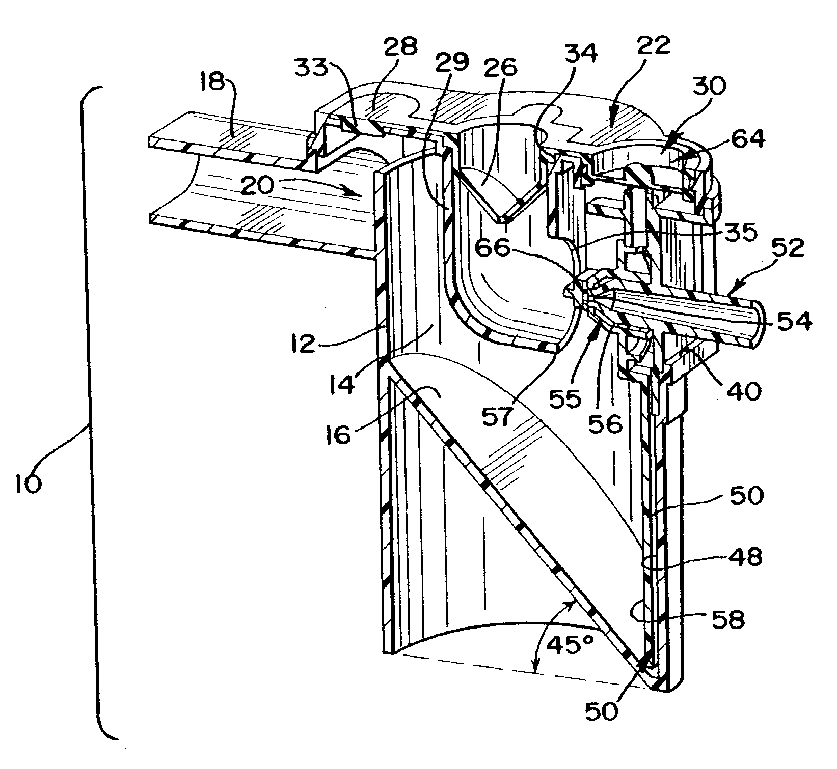
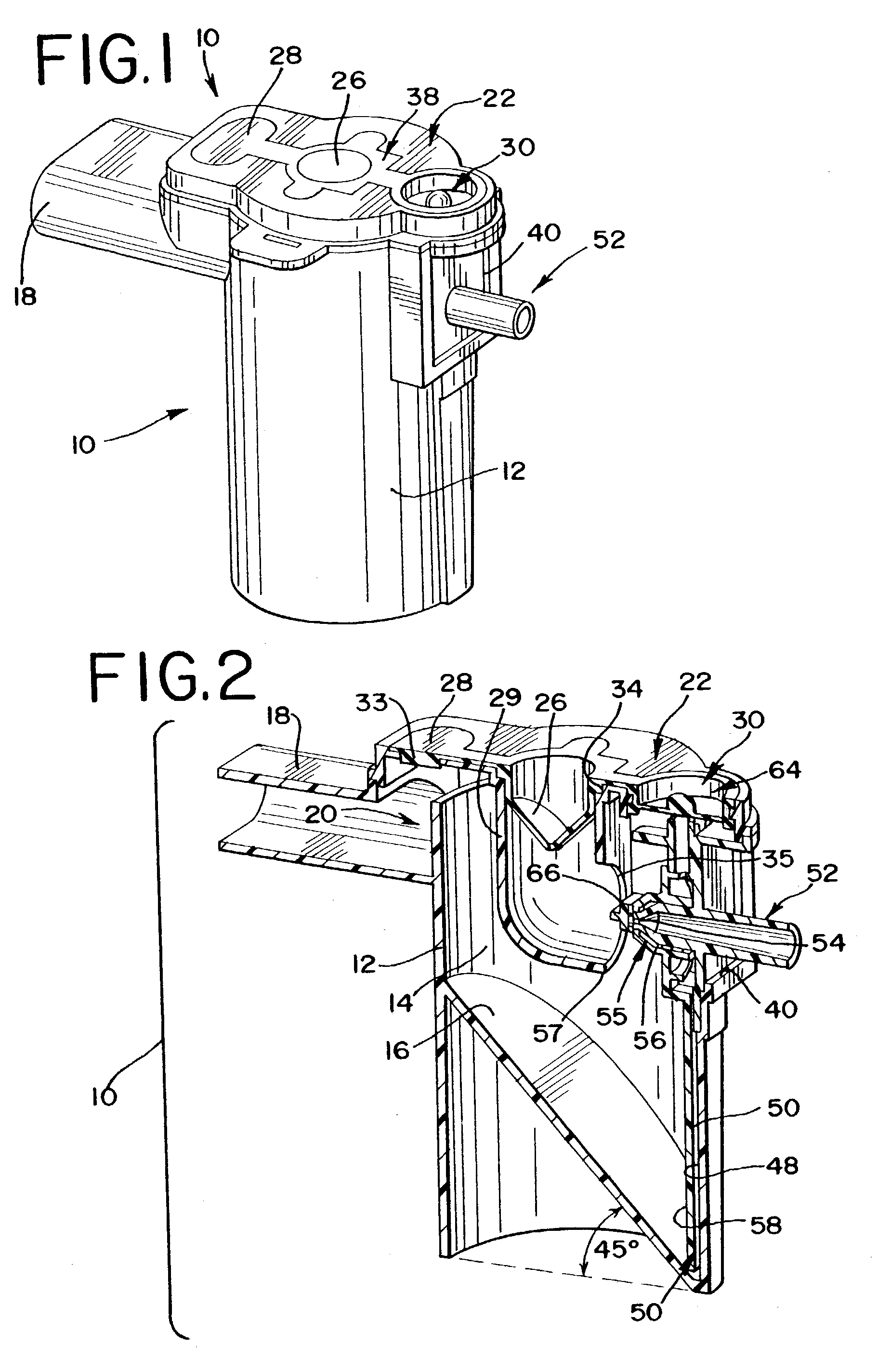
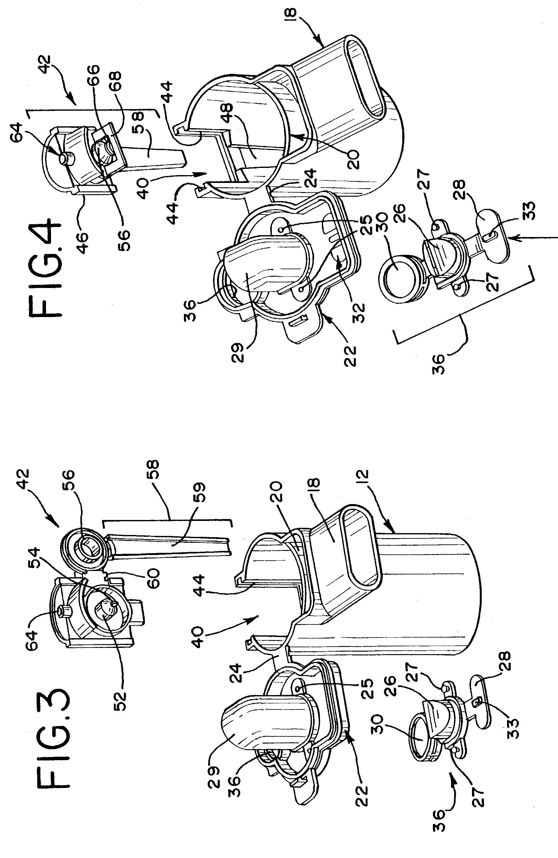
[0053] A preferred embodiment of a nebulizer 10 for nebulizing a fluid is shown in FIGS. 1-4. As used in this specification, the term "fluid" includes, without limitation, a fluid comprising a medicine, whether in the form of an emulsion, suspension or solution, that can be nebulized into an aerosol.

[0054] The nebulizer includes a housing 12 consisting of a chamber 14 that is suited to receive and hold a fluid. The chamber is preferably substantially cylindrical, however any of a number of shapes may be used. The chamber 14 includes an angled bottom portion 16 so that any fluid in the chamber will be directed toward one region of the bottom of the chamber to facilitate removal of all the fluid. In one embodiment, the bottom portion 16 is set at an approximate 45 degree angle in order to reduce wastage by maximizing the amount of fluid that is evacuated from the chamber for nebulization. An air outlet 18 extends away from the housing 12 and communicates with the chamber 14. A barrier...


PUM


Abstract

A nebulizer for efficiently and reliably delivering aerosolized fluid to an inhaling patient is disclosed. The nebulizer includes a fluid channel air inlet and fluid channel air inlet valve responsive to either a manual force external of the nebulizer, or a patient's breathing, to begin the nebulization process. Also provided is a method of providing nebulization including the steps of moving a fluid channel air inlet valve against a fluid channel air inlet so that a negative pressure may build up over the fluid in the fluid channel to draw fluid from the fluid reservoir and begin nebulization during inhalation.

Description

CROSS-REFERENCE[0001] This application claims the benefit of U.S. Application Serial No. 60 / 345,173 entitled "Nebulizer Apparatus and Method" filed Dec. 21, 2001, which is incorporated herein by reference.[0002] The present invention relates to an apparatus and method for generating an aerosol for delivery to a patient. More particularly, the present invention relates to a nebulizer configured to generate an aerosol in coordination with a patient's breathing. The present invention is also well suited for continuously generating an aerosol independent of a patient's breathing.[0003] Medical nebulizers that nebulize a fluid into an aerosol for inhalation by a patient are well-known devices commonly used for the treatment of certain conditions and diseases. Nebulizers have applications for conscious, spontaneously-breathing patients and for controlled, ventilated patients. As used in this specification, the term "patient" includes, without limitation, humans and animals.[0004] In nebul...

Claims


Application Information

Patent Timeline
Patent Type & Authority Applications(United States)
IPC IPC(8): A61M11/00A61M11/06A61M15/00
CPCA61M11/06A61M11/002A61M15/0091A61M15/0093
Inventor FOLEY, MARTIN P.GRYCHOWSKI, JERRYBLACKER, RICK
Owner TRUDELL MEDICAL INT INC
Why Eureka
Try Eureka