
Eureka
For R&D, Eureka makes reading and utilizing patents & technical documents easy.
Eureka AIR
Designed for self-driven R&D workflows. Generate viable solutions, solve complex R&D challenges, empower your innovation with AI.

Eureka Materials
Designed for material experts only. Revolutionize your material R&D, from search, analyze, to developing new materials.

TechResearch
Generate reliable direction feasibility study reports for your R&D in just a few steps.

TechSeek
Discover and master advanced knowledge NOW. Basics, ideas, possibilities, all at once.

TechMind
As an expert in R&D Theories, TechMind can generates customized viable solutions instantly.

TechRisk
Analyze your overall solution with one click, know your potential R&D risks in advance.

TechMonitor
Get weekly tech updates, stay abreast of the latest tech innovations and key insights.
Flow sensor
- Summary
- Abstract
- Description
- Claims
- Application Information
AI Technical Summary
Problems solved by technology
Method used
Image

Examples
Embodiment Construction
)
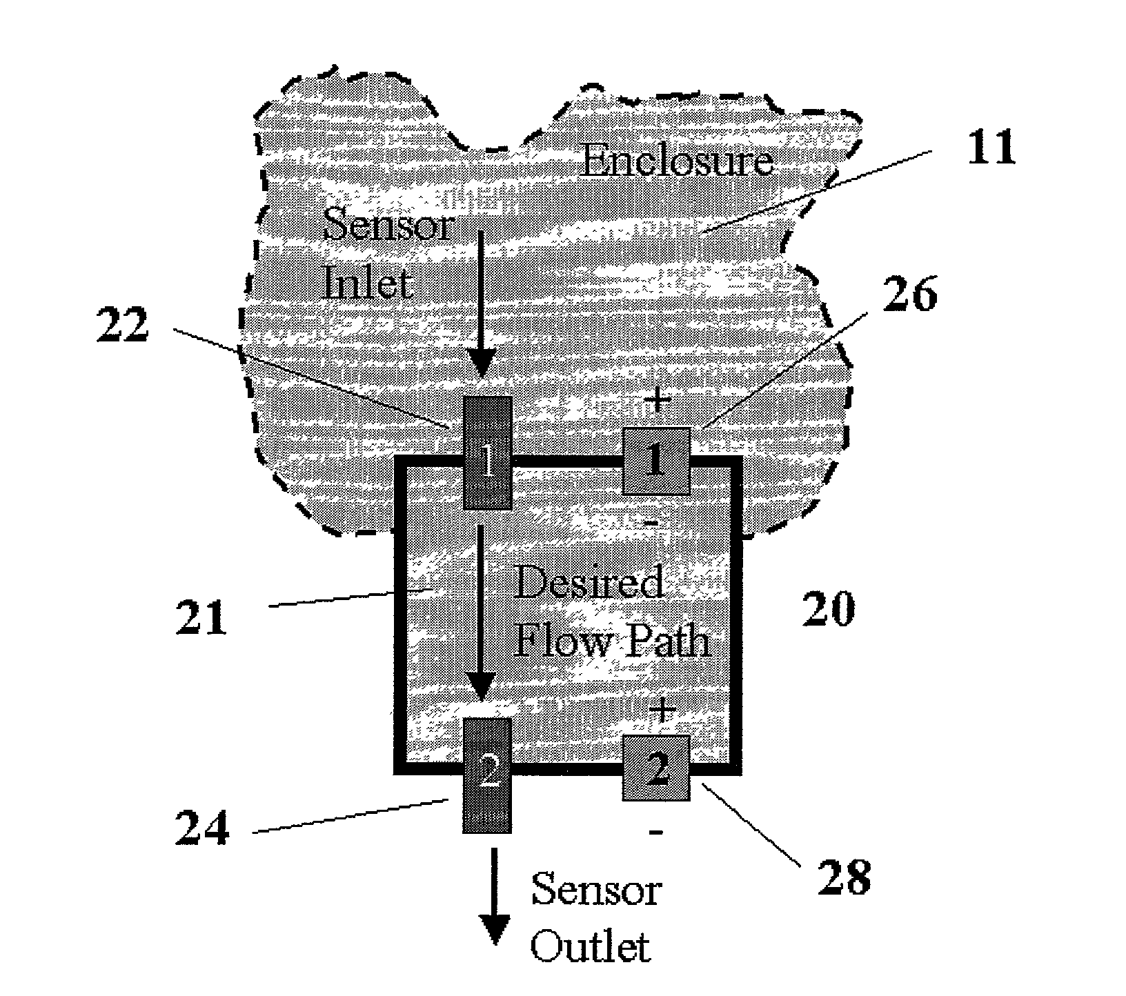
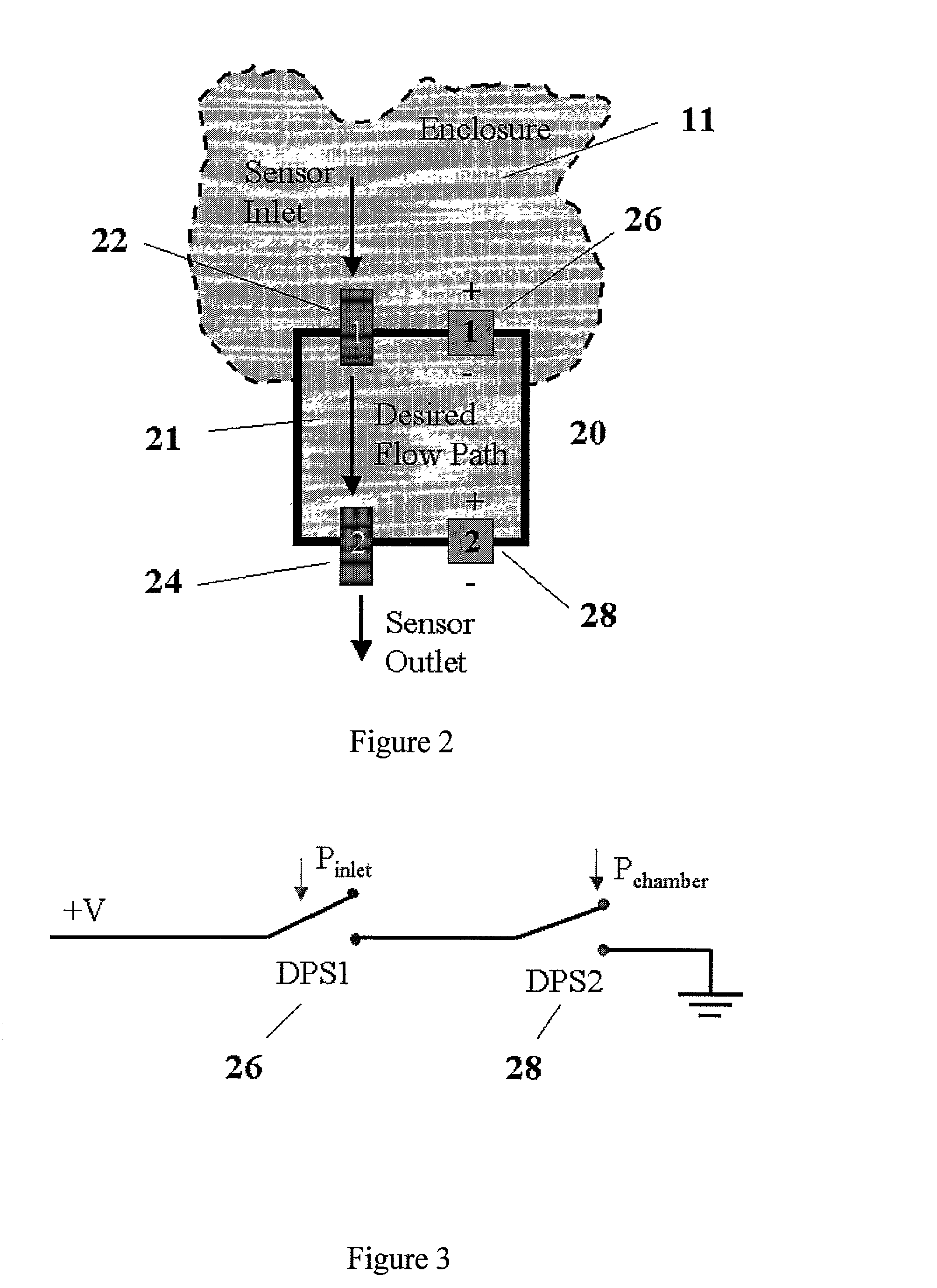
[0020] The purge gas flow sensor of the present invention utilizes differential pressure and detects the flow of purge gas electronically and operates at very low pressures. Referring now to FIG. 2 there is shown the purge gas flow sensor 20 at the outlet of an enclosure 11. The sensor 20 has a sensor inlet restriction 22, a sensor outlet restriction 24 and first and second differential pressure switches (DPSs) 26 and 28.
[0021] As is shown in the circuit diagram of FIG. 3 the two DPSs 26 and 28 are connected in the embodiment of the present invention shown in that figure in series. As can be appreciated the DPSs 26 and 28 may be connected in another configuration. If either DPS 26, 28 is open the series circuit is opened and the sensor 20 detects the lack of purge gas outlet flow from sensor 20.
[0022] The sensor 20 ensures flow through the outlet of the enclosure 11 by utilizing a sealed chamber. If the sensor inlet restriction 22 is obstructed or blocked, the flow through the purg...
PUM
 Abstract
Description
Claims
Application Information
 - R&D Engineer
- R&D Manager
- IP Professional
- Industry Leading Data Capabilities
- Powerful AI technology
- Patent DNA Extraction
Browse by: Latest US Patents, China's latest patents, Technical Efficacy Thesaurus, Application Domain, Technology Topic, Popular Technical Reports.
© 2024 PatSnap. All rights reserved.Legal|Privacy policy|Modern Slavery Act Transparency Statement|Sitemap|About US| Contact US: help@patsnap.com