Paint roller case

a roller case and roller technology, applied in the field of roller cases, can solve the problems of wasting the roller case, affecting the quality of the product, and requiring separate tools, etc., and achieve the effect of saving the cost and complexity of the invention, and avoiding the use of separate tools

Inactive Publication Date: 2003-10-09
MYERS KENNETH W
View PDF0 Cites 18 Cited by
  • Summary
  • Abstract
  • Description
  • Claims
  • Application Information

AI Technical Summary

Benefits of technology

0005] One object of the present invention is to provide a means to store a ...

Problems solved by technology

Roller covers must be cleaned after each use because dried paint would render a roller cover useless.
Anyone skilled in the art will recognize that this operat...

Method used


Image

  • Paint roller case
  • Paint roller case
  • Paint roller case

Examples


Embodiment Construction

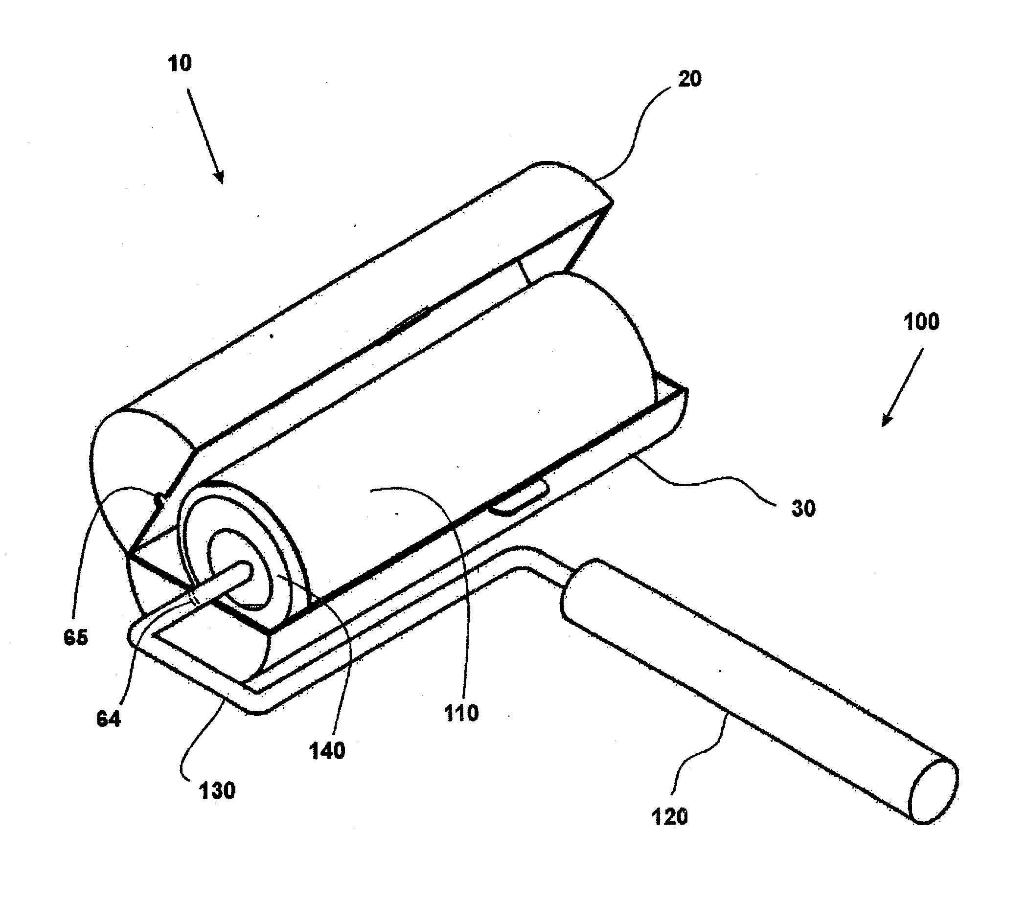
[0017] In accordance with the present invention, FIG. 1 shows a perspective view of the paint roller case 10, and paint roller assembly 100.

[0018] Paint roller assembly 100 comprises roller handle 120, roller shaft 130, roller 140 and roller cover 110. Roller cover 110 is shown inside case bottom 30. Roller shaft 130 protrudes through a hole 64 in case bottom 30. Hole 65 in case top 20 corresponds to the hole 64 in case bottom 30, providing clearance for roller shaft 130.

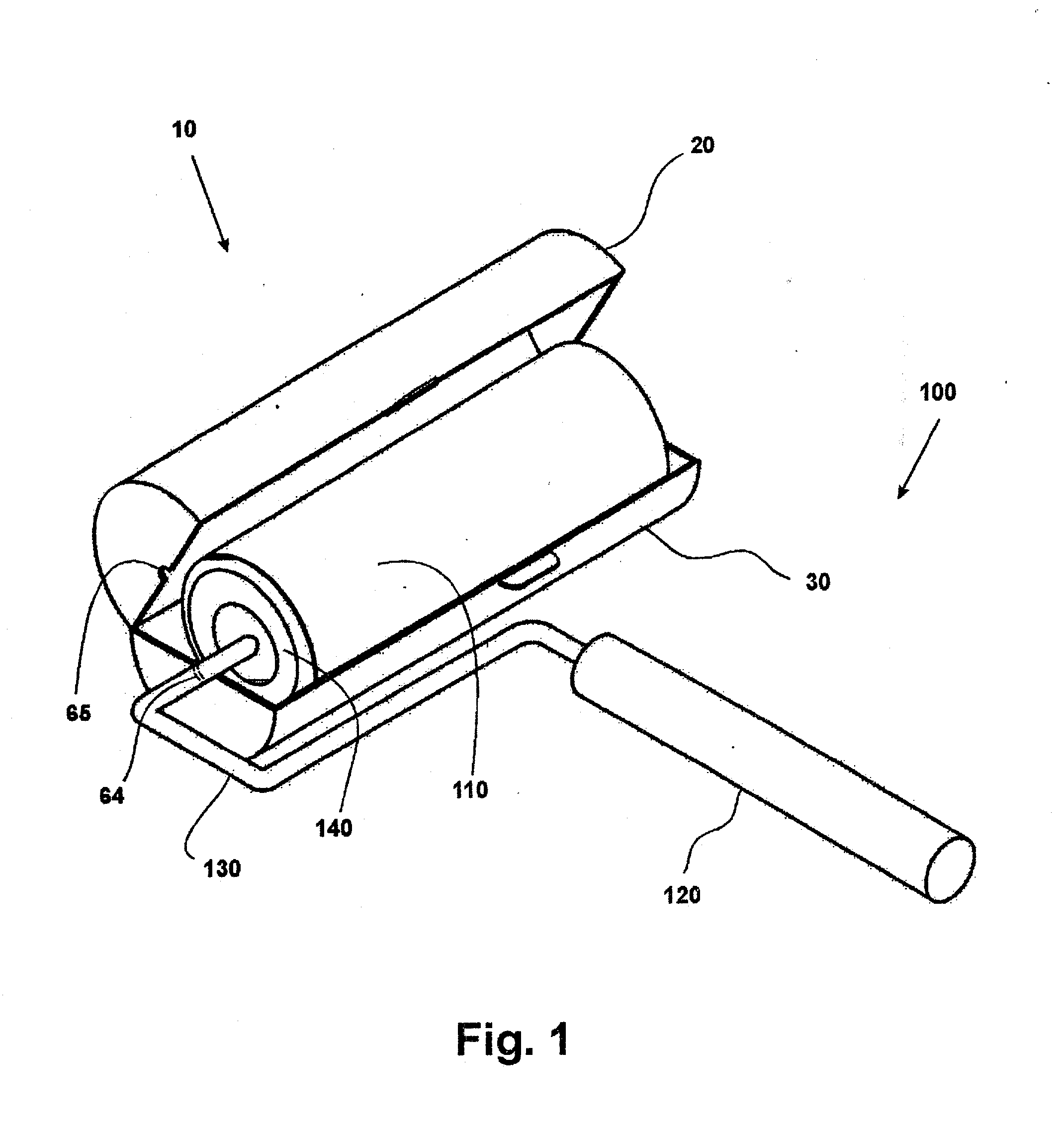
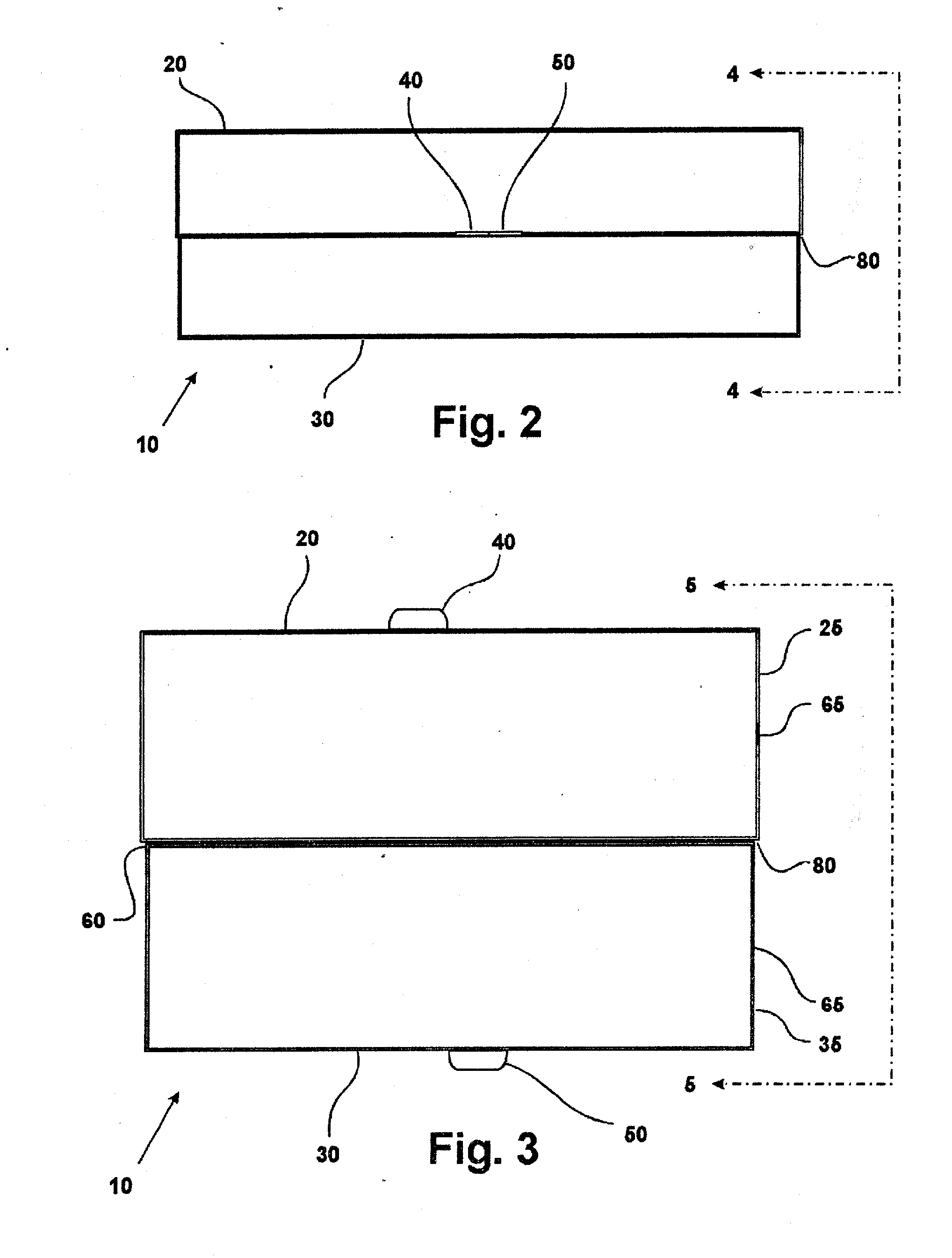
[0019] FIG. 2 shows paint roller case 10 in the closed position. Case bottom 30 is slightly overlapped at 80 by case top 20. This provides for a substantially airtight condition. Case top 20 and case bottom 30 are maintained in the closed position by friction interaction between top latch 40 and bottom latch 50.

[0020] FIG. 3 shows paint roller case 10 in the opened position. Case top 20 is slightly longer than case bottom 30, creating overlap 80. This provides the substantially airtight condition. Plastic hinge 60 i...


PUM


Abstract

The present invention involves a molded plastic housing with an integral plastic hinge that opens to receive a wet paint roller cover and roller handle assembly. The present invention provides a hole to allow the paint roller handle shaft to protrude out of the housing. The present invention provides a relatively airtight housing by means of molded overlapping ridges.

Description

I FIELD OF THE INVENTION[0001] This invention relates to an apparatus for storing a paint roller cover and handle assembly to keep the paint fresh and thus avoid cleaning the roller cover between painting sessions.II BACKGROUND OF THE INVENTION[0002] The most common method of painting objects such as the walls and ceilings of a house or other structure is by using a paint roller. Roller covers must be cleaned after each use because dried paint would render a roller cover useless. If the roller will be used again in a fairly short amount of time, a method of storing the paint-filled roller would free the user from the time-consuming and messy process of cleaning it between uses.[0003] The present invention provides a simple, inexpensive, and compact means of storing a paint-filled roller whereby the paint will remain fresh and uncured. Prior attempts have been made to achieve this objective. For example, U.S. Pat. No. 5,440,853 discloses a roller cover storing method. This invention ...

Claims


Application Information

Patent Timeline
IPC IPC(8): B44D3/12B65D8/00B65D83/10
CPCB44D3/125
Inventor MYERS, KENNETH W.
Owner MYERS KENNETH W
Why Eureka
Try Eureka