Card-edge connector and card member

Inactive Publication Date: 2003-11-20
NEC CORP
View PDF5 Cites 3 Cited by
  • Summary
  • Abstract
  • Description
  • Claims
  • Application Information

AI Technical Summary

Problems solved by technology

In this respect, the above conventional card-edge connector has the following problems left unsolved.
Further, the card-edge electrodes cannot be extended to the edge of the circuit board for production reasons.

Method used


Image

  • Card-edge connector and card member
  • Card-edge connector and card member
  • Card-edge connector and card member

Examples


Embodiment Construction

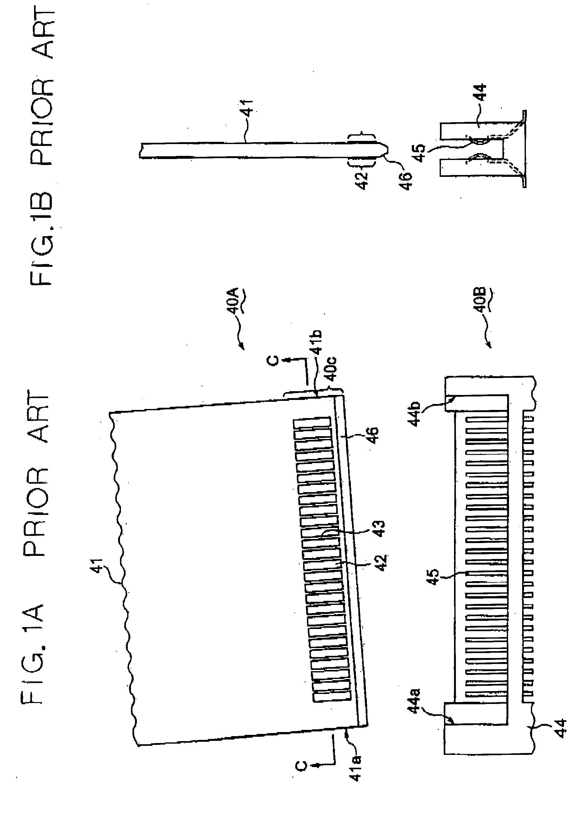
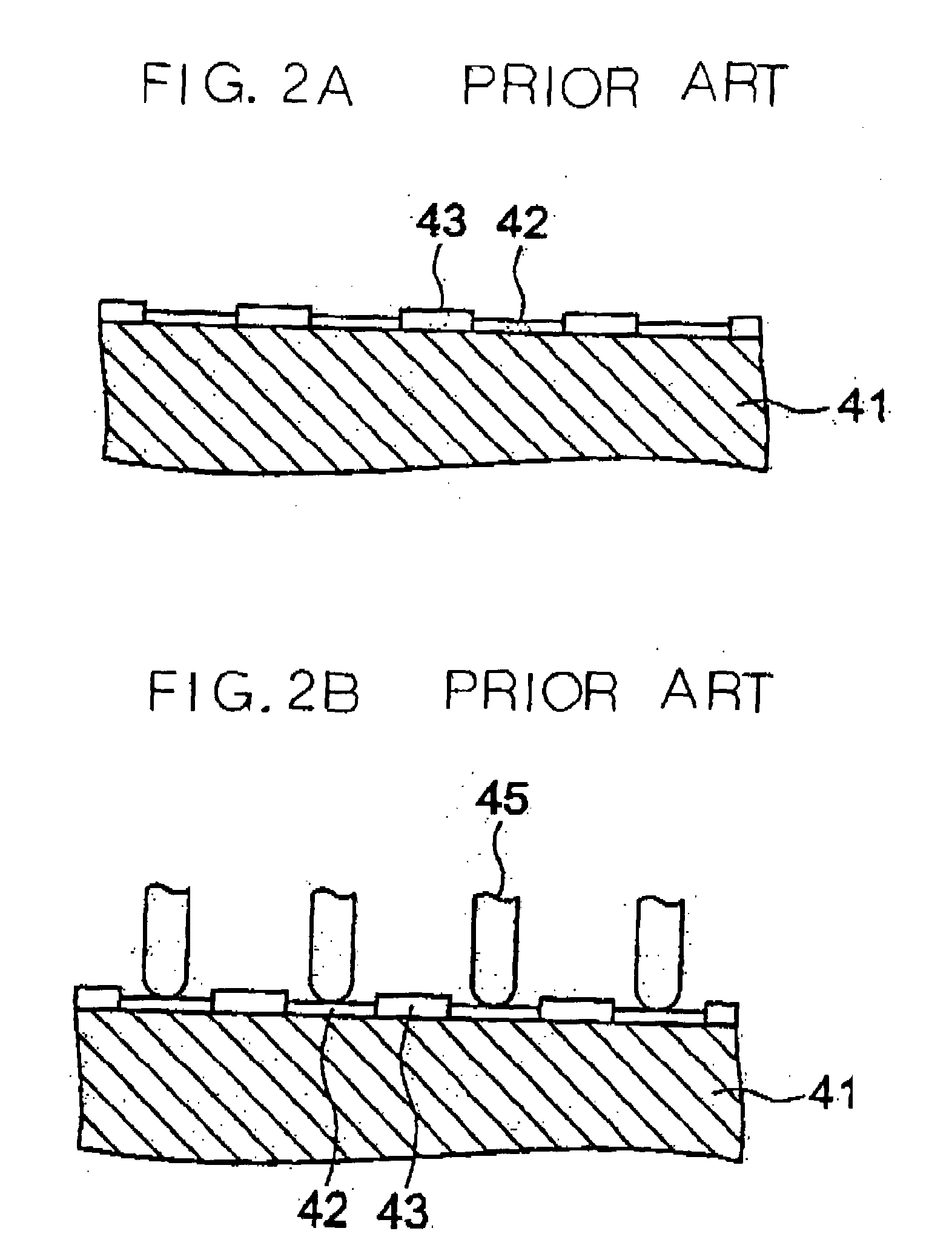
[0029] To better understand the present invention, brief reference will be made to a conventional card-edge connector, shown in FIGS. 1A and 1B. As shown, the card-edge connector, generally 40, is made up of a card member 40A and a connector 40B provided on a board, which is affixed to, e.g., an electronic apparatus not shown. The card member 40A includes a printed circuit, not shown, and an electrode portion 40C that adjoins one edge of the card member 40A. The electrode portion 40C includes a plurality of card-edge electrodes 42 formed on a circuit board 41. Solder resist 43 surrounds the card-edge electrodes 42. The edge of the circuit board 41, adjoining the electrode portion 40C, is formed with a taper 46. The card-edge electrodes 42, solder resist 43 and taper 46 are formed on both sides of the circuit board 41.

[0030] The connector 40B on the board side includes a housing 44 for receiving the card member 40A and contacts 45 corresponding one-to-one to the card-edge electrodes ...


PUM


Abstract

A card-edge connector of the present invention includes a card member including a circuit board and a plurality of card-edge electrodes arranged on the circuit board. A connector is affixed to a stationary hoard and includes a plurality of contacts corresponding one-to-one to the card-edge electrodes. The card member further includes an insulation cover covering an area where the card-edge electrodes are arranged and formed with a plurality of slots via which the card-edge electrodes each are partly exposed to the outside. When the card member is inserted into the connector, the card-edge electrodes and contacts are electrically connected to each other.

Description

[0001] 1. Field of the Invention[0002] The present invention relates to a card-edge connector and a card member for an electronic apparatus and more particularly to a card-edge connector and a card member allowing a minimum of defective contact to occur and allowing a minimum of impurities to deposit on the contact points of contacts.[0003] 2. Description of the Background Art[0004] A conventional card-edge connector applicable to various electronic apparatuses is generally made up of a card member with a printed circuit board and a connector affixed to a board, which is included in an electronic apparatus. The card member includes a circuit board, a plurality of card-edge electrodes arranged on the circuit board, and solder resist surrounding the card-edge electrodes. The connector includes a housing for receiving the card member and contacts corresponding one-to-one to the card-edge electrodes.[0005] The conventional card-edge connector described above is superior in electric char...

Claims


Application Information

Patent Timeline
IPC IPC(8): G06K7/00H01R13/64H01R13/52H01R13/631H05K1/11
CPCH01R13/631H01R12/721H05K2201/10598H05K1/117
Inventor KAMIYAMANE, SHIN
Owner NEC CORP
Why Eureka
Try Eureka