Support Apparatus

Inactive Publication Date: 2003-12-04
TSAI DAVID
View PDF0 Cites 49 Cited by
  • Summary
  • Abstract
  • Description
  • Claims
  • Application Information

AI Technical Summary

Benefits of technology

0008] The positioning device includes a mount secured to the first tube and a latch movably mounted on the mount between an engaging position where the latch engages with the rod and a rele

Problems solved by technology

However, the positioning device cannot help the tubes be adjust

Method used


Image

  • Support Apparatus
  • Support Apparatus
  • Support Apparatus

Examples


Embodiment Construction

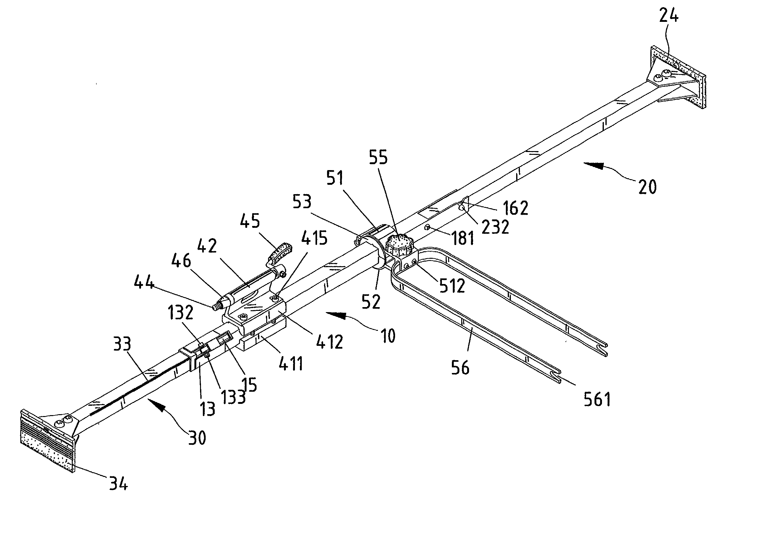
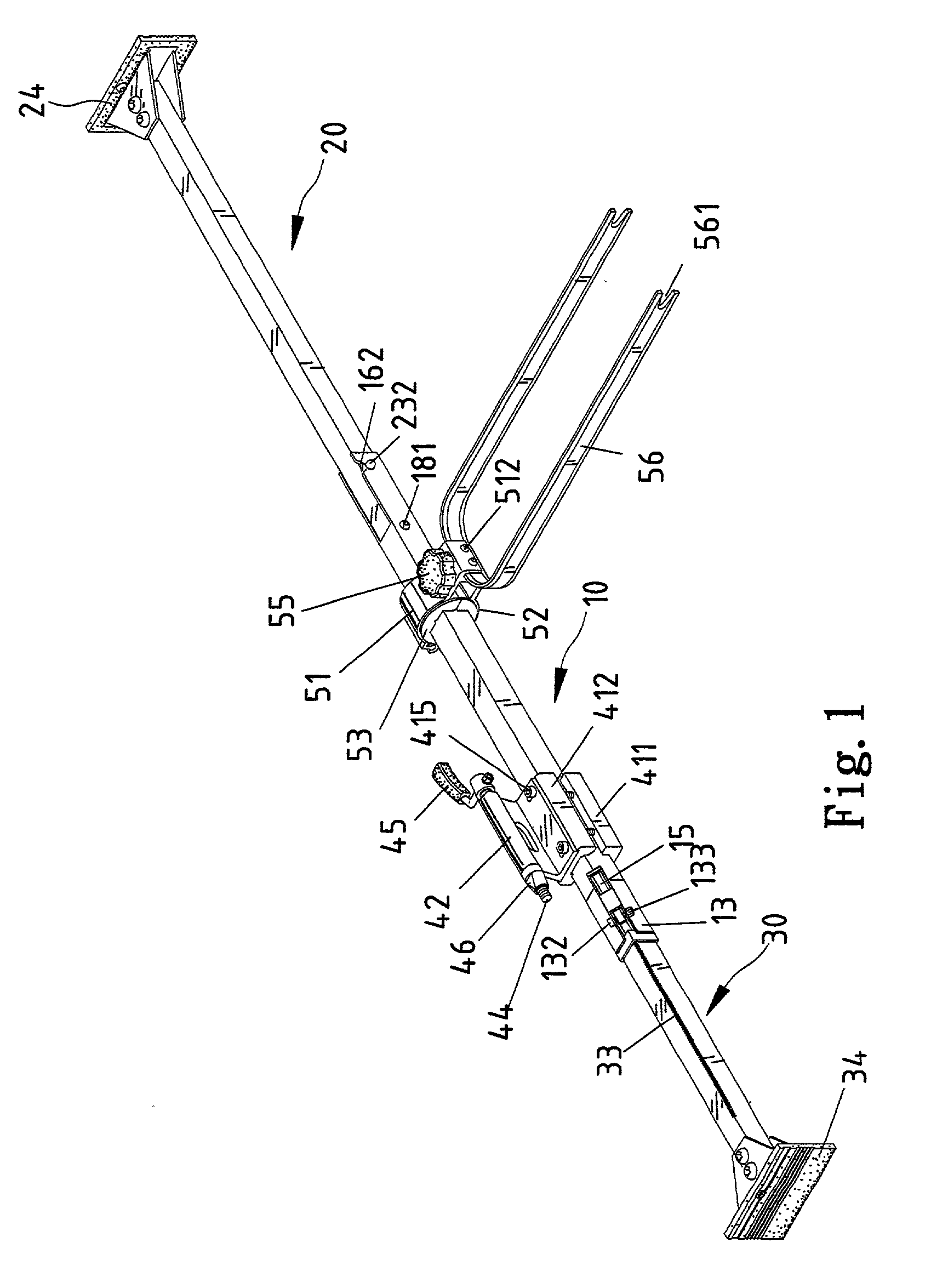
[0034] Referring to the drawings, a support apparatus according to the preferred embodiment of the present invention includes a first tube 10, a second tube 20 pivotally connected with the first tube 10 and a rod 30 telescopically inserted in the first tube 10.

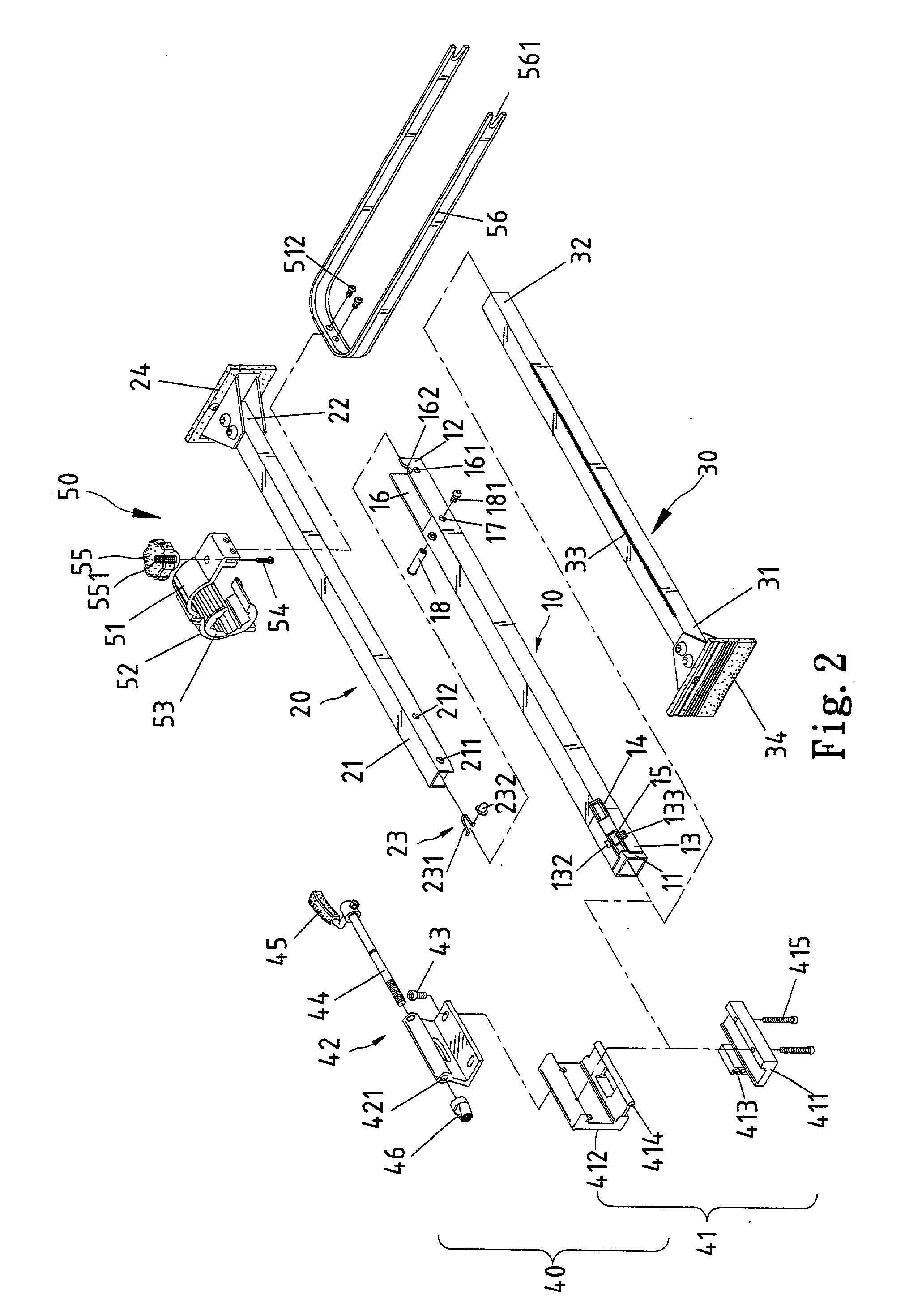
[0035] Referring to FIGS. 1 and 2, the first tube 10 is formed with a first end 11 and a second end 12. The rod 30 can be inserted into the first tube 10 through the end 11. A positioning device is installed on the first tube 10 near the first end 11 in order to retain the rod 30 in position relative to the first tube 10.

[0036] Further referring to FIG. 3, the positioning device includes a slot 111 defined in the first tube 10 near the first end 11. The positioning device includes a mount 13 secured to the first tube 10 and a latch 15 mounted on the mount 13. The mount 13 includes two lateral portions secured to the first tube 10 and an intermediate portion formed between the lateral portions. The slot 111 is located between t...


PUM


Abstract

A support apparatus includes a first tube, a second tube pivotally connected with the first tube, a rod telescopically connected with the first tube and a positioning device for retaining the rod in position relative to the first tube. The positioning device includes a mount secured to the first tube and a latch movably mounted on the mount between an engaging position where the latch engages with the rod and a releasing position where the latch releases the rod. The mount includes two lateral portions secured to the first tube. The latch is pivotally mounted on the lateral portions of the mount. Each of the lateral portions of the mount defines an aperture. The latch defines an aperture. A bolt is inserted through the aperture defined in each of the lateral portions of the mount and the aperture defined in the latch. The mount includes an intermediate portion formed between the lateral portions. A spring is arranged between the intermediate portion of the mount and the latch for retaining the latch in the engaging position. The latch includes a first section for engagement with the rod and a second section to be operated so as to move the latch between the engaging and releasing positions. The rod includes a series of teeth. The first section of the latch includes at least one tooth formed thereon for engagement with at least one of the teeth formed on the rod in the engaging position.

Description

BACKGROUND OF INVENTION[0001] 1. Field of Invention[0002] The present invention is related to a support apparatus.[0003] 2. Related Prior Art[0004] Taiwanese Patent Publication No. 465688 teaches a positioning device for elements movable relative to each other. In specific, the elements movable relative to each other are a first tube and a second tube for insertion in the first tube. The positioning device includes a clamp and a bolt. The clamp includes an internal face consisting of a first section for receiving the first tube and a second section for receiving the second tube. The clamp includes two separate claws each defining an aperture for receiving the bolt. The bolt can be engaged with a nut in order to move the claws toward to each other. Thus, the first and second tubes are retained in position by means of the positioning device. However, the positioning device cannot help the tubes be adjusted to an adequate length for tight abutment against two surfaces[0005] The present...

Claims


Application Information

Patent Timeline
IPC IPC(8): A47F5/00A47F5/08B60P7/15B62H3/00B62H3/04F16M13/00F16M13/02
CPCA47F5/0006A47F5/0838B60P7/15B62H3/00F16M11/28F16M13/00F16M13/02F16M11/10B62H3/04
Inventor TSAI, DAVID
Owner TSAI DAVID
Why Eureka
Try Eureka