
Optical disc case structure

a technology of optical discs and case structures, applied in the direction of instruments, packaging goods, transportation and packaging, etc., can solve the problems of not being able to provide satisfactory results with respect to the durability of holding members, and the disposition of holding members 18 not being durable, so as to reduce the dimensional size and the occupied space. the effect of small siz

Inactive Publication Date: 2003-12-25
PRORIT CORP
View PDF5 Cites 4 Cited by
  • Summary
  • Abstract
  • Description
  • Claims
  • Application Information

AI Technical Summary

Benefits of technology

[0011] Furthermore, it is another object of the invention to provide, an optical disc case structure that allows an easy take-up of the disc when the case structure is opened.
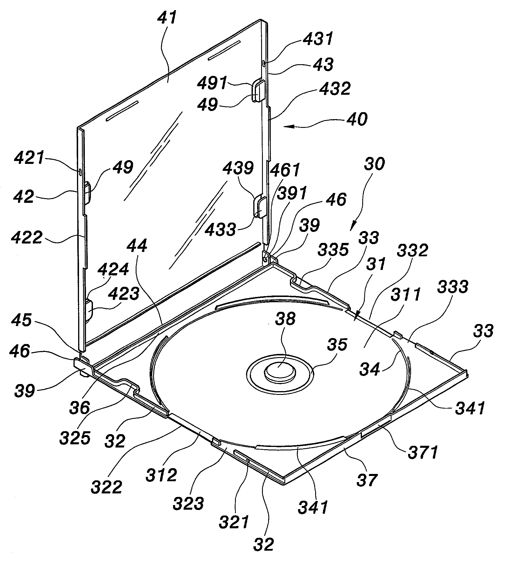
[0012] To accomplish the above and other objectives, an optical disc case structure of, the invention comprises a bottom cover and a top cover that are pivotably mounted to each other. The bottom cover defines a placement space in which the optical disc is disposed. Within the placement space, a positioning member is placed to position the optical disc. The top cover is further provided with transversal flanges placed in such a manner that once the top and bottom covers fold onto each other, the transversal flanges press on the outer peripheral edge of the optical disc, thereby securely immobilizing the optical disc within the closed case structure. Once the top and bottom covers are unfolded, the optical disc is released from clamping and can be freely picked up. The optical disc is thereby securely protected within the case structure.

Problems solved by technology

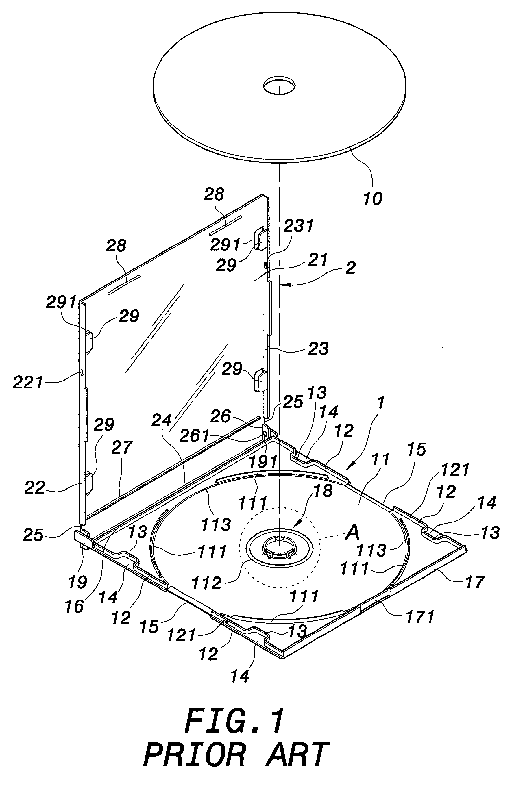
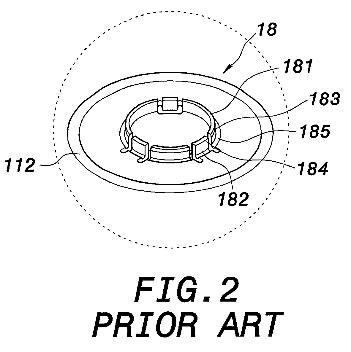
Although a resulting deviation may not be significant, this deficiency however may cause the holding member 18 not to be durable.
However, this disposition does not provide satisfactory results with respect to the durability of the holding member.

Method used


Image

  • Optical disc case structure
  • Optical disc case structure
  • Optical disc case structure

Examples


Embodiment Construction

[0025] Wherever possible in the following description, like reference numerals will refer to like elements and parts unless otherwise illustrated.

[0026] Referring to FIG. 5 and FIG. 9, two perspective views schematically show a structure of disc case according to an embodiment of the invention. A disc case 3 comprises a bottom cover 30 and a top cover 40 that are mounted to each other via a pivot hinge. The bottom cover 30 and the top cover 40 can thereby rotatably unfold or fold onto each other to achieve opening or closing of the disc case 3. The disc case 3 is closed up with both bottom and top covers 30, 40 covering on each other.

[0027] The bottom cover 30 includes a bottom board 31. A front peripheral projection 32 and a rear peripheral projection 33 are projecting proximate to a front outer periphery and a rear outer periphery of the bottom cover 31. Each of the front and rear peripheral projections 32, 33 is comprised of a pair of projecting elements symmetrical to each other...


PUM

PropertyMeasurementUnit
thicknessaaaaaaaaaa
diameteraaaaaaaaaa
heightaaaaaaaaaa

Abstract

An optical disc case structure comprises a bottom cover and a top cover assembled with each other. A conically pillared positioning member is placed on the bottom cover to position the optical disc by engaging the central hole thereof. A central protruding ring and a peripheral protruding ring are formed on the bottom cover where is placed the optical disc. A plurality of flanges further inwardly protrude from two sides of the top cover parallel to the top cover. Hence arranged, the flanges receive advertisement cards and further press on the optical disc once the top and bottom covers fold onto each other.

Description

[0001] 1. Field of the Invention[0002] The invention relates to an optical disc case structure. More particularly, the invention relates to an optical disc case structure that is provided with peripheral clamping members for immobilizing the optical disc in the case.[0003] 2. Description of the Related Art[0004] Referring to FIG. 1 and FIG. 2, two perspective views schematically show the structure of a conventional optical disc case. The conventional disc case usually receives a standard disc 10 having a diameter of 12 cm. The disc case is constructed from a bottom cover 1 and a top cover 2 assembled with each other. The bottom cover 1 includes a bottom board 11 whose front and rear outer peripheries are respectively provided with front and rear peripheral projections 12 that are symmetrical to each other. Each front / rear peripheral projection 12 is composed of two projecting elements that are spaced apart from each other via a groove 15 and, furthermore, respectively define a flang...

Claims


Application Information

Patent Timeline
Patent Type & Authority Applications(United States)
IPC IPC(8): G11B33/04
CPCG11B33/0427
Inventor YANG, CHIN-TIENPONG, CHI-WEI
Owner PRORIT CORP
Learn More