Transverse rod connector

Active Publication Date: 2011-02-24
K2M
View PDF19 Cites 52 Cited by
  • Summary
  • Abstract
  • Description
  • Claims
  • Application Information

AI Technical Summary

Benefits of technology

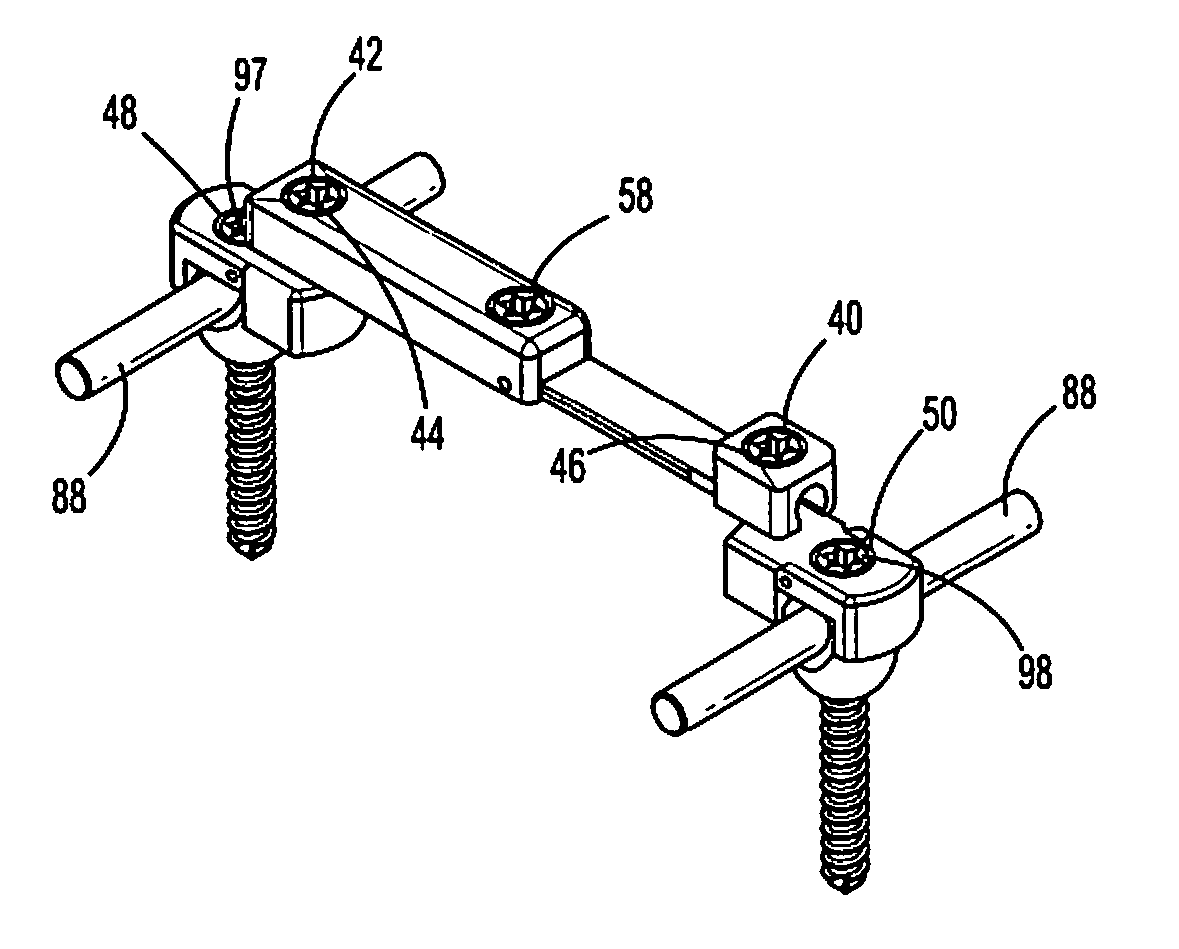
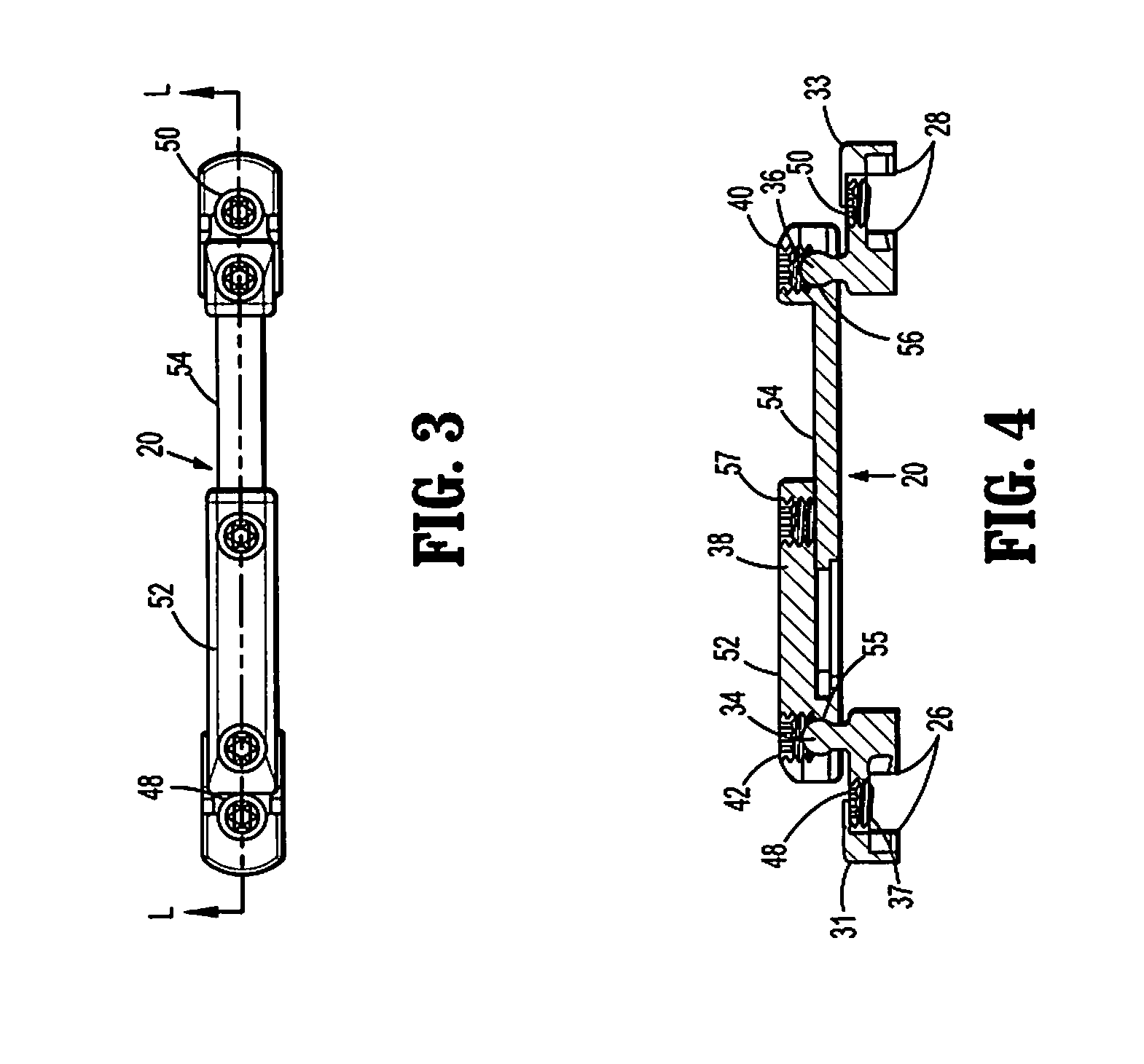
[0012]In yet another embodiment, the first and second ends of the elongate members may each include a receptacle portion. The first and second connection members may each include a ball joint. The ball joints may be received in the respective receptacle portions for multidirectional positioning of the first and second connection members with respect to the elongate member. The elongate member may include first and second screws dimensioned to be received in the respective receptacle portions. The first and second screws may securely fix the ball joints in the respective receptacle portions to fix the orientation of the connection members with respect to the elongate member.
[0013]In still another embodiment, the first and second ends of the elongate members may each include a ball joint. The first and second connection members may each include a socket portion. The hall joints may be receive

Problems solved by technology

Conventional efforts to meet this need have fallen short of the desired transverse connector configuration.
The two connector members are connected one to the other by a fixed member, thereby not allowing adjustment b

Method used


Image

  • Transverse rod connector
  • Transverse rod connector
  • Transverse rod connector

Examples


Example

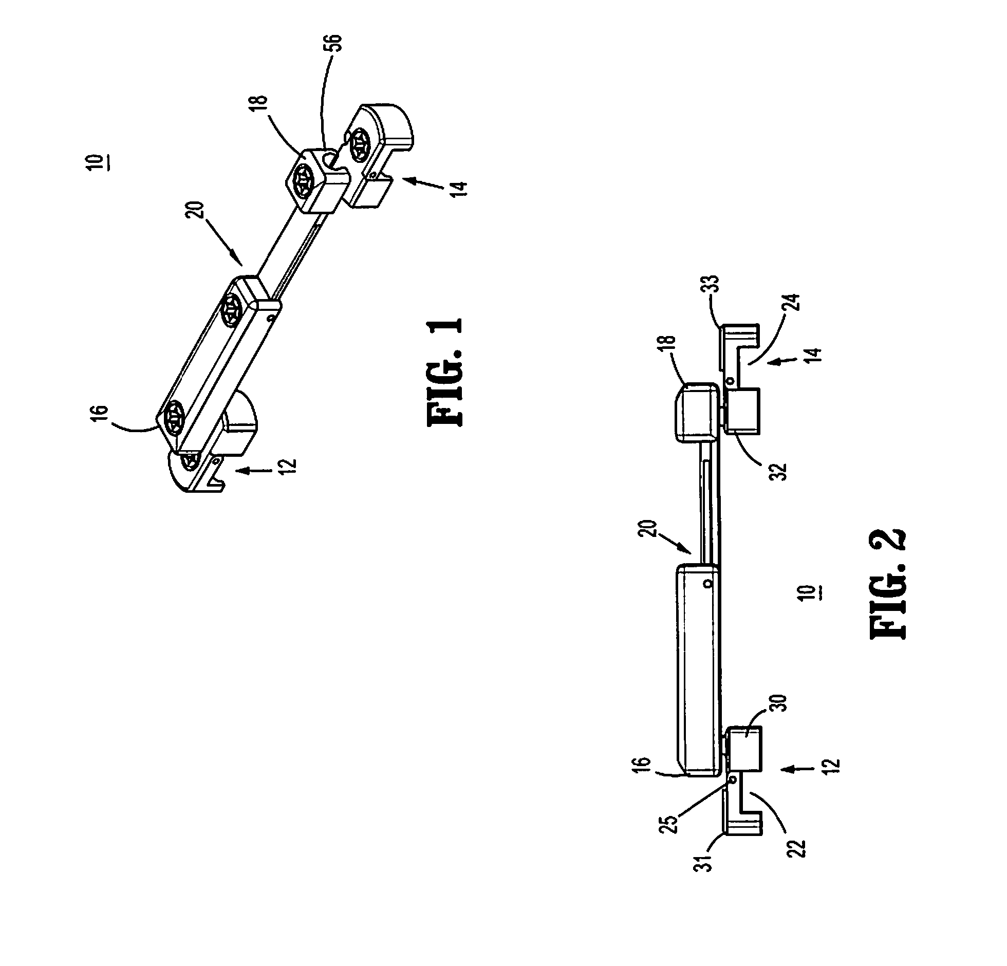
[0042]Various embodiments of the presently disclosed transverse rod connector will now be described in detail with reference to the drawings, wherein like reference numerals identify similar or identical elements. In the drawings and in the description that follows, the term “proximal,” will refer to the end of a device or system that is closest to the operator, while the term “distal” will refer to the end of the device or system that is farthest from the operator. In addition, the term “cephalad” is used in this application to indicate a direction toward a patient's head, whereas the term “caudad” indicates a direction toward the patient's feet. Further still, for the purposes of this application, the term “medial” indicates a direction toward the middle of the body of the patient, whilst the term “lateral” indicates a direction toward a side of the body of the patient (i.e., away from the middle of the body of the patient). The term “posterior” indicates a direction toward the pa...


PUM


Abstract

A transverse rod connector includes an elongate member having first and second ends and first and second connection members. The first and second connection members are connected with first and second ends, respectively. The first and second connection members are configured for multidirectional positioning with respect to the elongate member. The first and second connection members are each dimensioned to be selectively and releasably secured to a bone anchor. The elongate member is longitudinally adjustable.

Description

CROSS-REFERENCE TO RELATED APPLICATION[0001]The present application claims the benefit of and priority to U.S. Provisional Patent Application Ser. No. 61 / 274,820, filed Aug. 21, 2009, the disclosure of which is herein incorporated by reference in its entirety.BACKGROUND[0002]1. Technical Field[0003]The present disclosure relates to a device for interconnecting bone anchors and, more particularly, to a transverse rod connector configured for multidirectional articulation with respect to the bone anchor.[0004]2. Background of Related Art[0005]Disease, the effects of aging, or physical trauma resulting in damage to the spine has been treated in many instances by fixation or stabilization of the effected vertebra. A wide variety of spinal fixation apparatuses have been employed in surgical procedures for correcting spinal injuries and the effects of spinal diseases. Many of these apparatuses commonly use a pair of longitudinal rods running in a relatively parallel relationship to each o...

Claims


Application Information

Patent Timeline
IPC IPC(8): A61B17/70
CPCA61B17/7032A61B17/7052A61B17/7037A61B17/7043A61B17/7007A61B17/7008
Inventor BARRUS, MICHAELJONES, SCOTTBROWN, STEVEN A.
Owner K2M
Why Eureka
Try Eureka