Electrostatic filter

Inactive Publication Date: 2004-02-12
HANSOM ENVIRONMENTAL PROD
View PDF18 Cites 50 Cited by
  • Summary
  • Abstract
  • Description
  • Claims
  • Application Information

AI Technical Summary

Benefits of technology

0006] The smaller micron and sub-micron particles also have a greater visual effect in polluted atmospheres. For the same total mass, smaller particles will generally be dispersed over a great

Problems solved by technology

Stringent controls are imposed by regulatory authorities on the emission of hazardous air p

Method used


Image

  • Electrostatic filter
  • Electrostatic filter
  • Electrostatic filter

Examples


Embodiment Construction

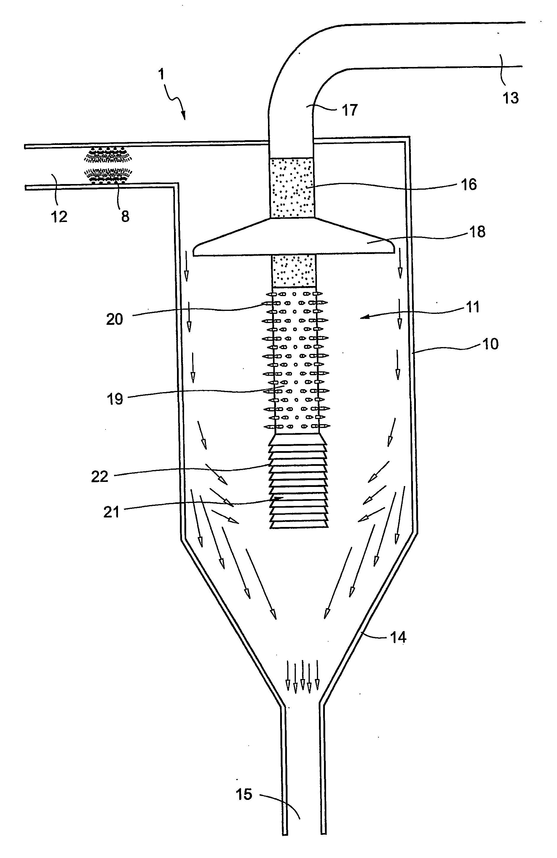
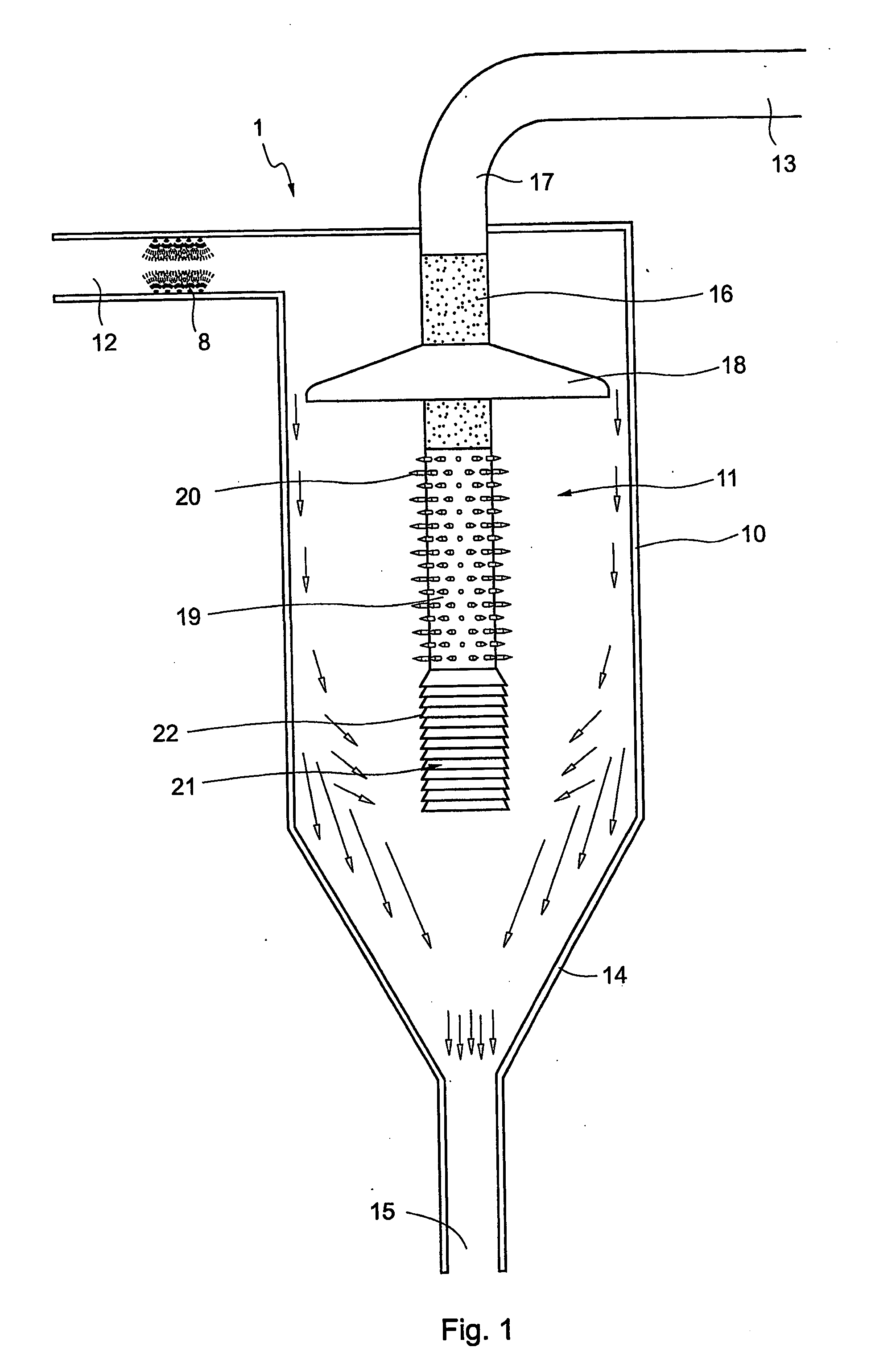
[0032] The electrostatic filter of FIG. 1 comprises a housing 1 having a cylindrical wall 10 defining a chamber 11. At least the inside surface of the wall 10 is a conductive earthed surface. The housing has an inlet 12 adapted to receive "dirty" gas containing dust particles and other pollutants. The bottom of housing 10 is tapered to form a collection hopper 14 which receives dust particles and other pollutants removed from the inlet gas as described below. The hopper 14 communicates with an outlet 15 for discharging the collected dust particles as well as water which may be used to wash down the wall 10. The filter also has an outlet 13 for "clean" gas from which the dust particles and pollutants have been removed.

[0033] The wall 10 is typically circular in cross section, and the inlet 12 may be located tangentially to the housing so that the inlet gas enters the chamber 11 in a swirling action. Water sprays 8 may be used at the inlet to enhance dust removal and cool the incoming...


PUM


Abstract

An electrostatic filter (1) has a chamber (11) into which a gas stream is introduced. An ioniser (19) in the form of an electrode array (20) is located in the chamber (11) and creates an ionising zone through which the gas stream passes. A charged outlet (21) is located downstream from the ioniser (19). As the gas stream passes through the ionising zone, the unwanted particles therein are charged and urged away from the outlet (21) by the ioniser (19). Charged particles approaching the outlet (21) are also electrostatically repelled therefrom, permitting "clean" gas to be extracted through the outlet.

Description

[0001] THIS INVENTION relates to an electrostatic filter suitable for separating (solid or liquid) particles from a gas stream. The invention is particularly suitable for controlling air pollution from industrial processes, but is not limited to that particular application.[0002] For example, the invention may also be used to filter particles from air supplied to air conditioning or ventilation systems, and to remove dust particles from airstreams in vacuum cleaning devices. The invention may also be used generally for separation of particles (solid or liquid) from a gas stream as a precursor to further processing of the gas stream, e.g. in recovery of fly ash and other fines in cement works.[0003] Stringent controls are imposed by regulatory authorities on the emission of hazardous air pollutants, and these are likely to become even more stringent as pollution levels increase. Of particular concern are toxic trace metals and their compounds which exist in the form of small particle...

Claims


Application Information

Patent Timeline
IPC IPC(8): B03C3/12B03C3/41F01N3/01
CPCB03C3/12B03C3/15B03C3/41B03C2201/10F01N3/01Y02T10/20B03C2201/14B03C3/49B03C3/38Y02T10/12
Inventor TRUCE, RODNEY JOHN
Owner HANSOM ENVIRONMENTAL PROD
Why Eureka
Try Eureka