Joint of channel-lock pliers

a technology of channel lock and pliers, which is applied in the field of joint of a pair of channel lock pliers, can solve the problems of damage to equipment and injuring a person using the pliers

Inactive Publication Date: 2004-08-19
TING CHENG CHENG
View PDF2 Cites 32 Cited by
  • Summary
  • Abstract
  • Description
  • Claims
  • Application Information

AI Technical Summary

Problems solved by technology

Second, the nut (53) protrudes from the adjustable handle (30), is unsightly, may injure a person using the pliers or damage equipment on which the pliers are used.

Method used


Image

  • Joint of channel-lock pliers
  • Joint of channel-lock pliers
  • Joint of channel-lock pliers

Examples


Embodiment Construction

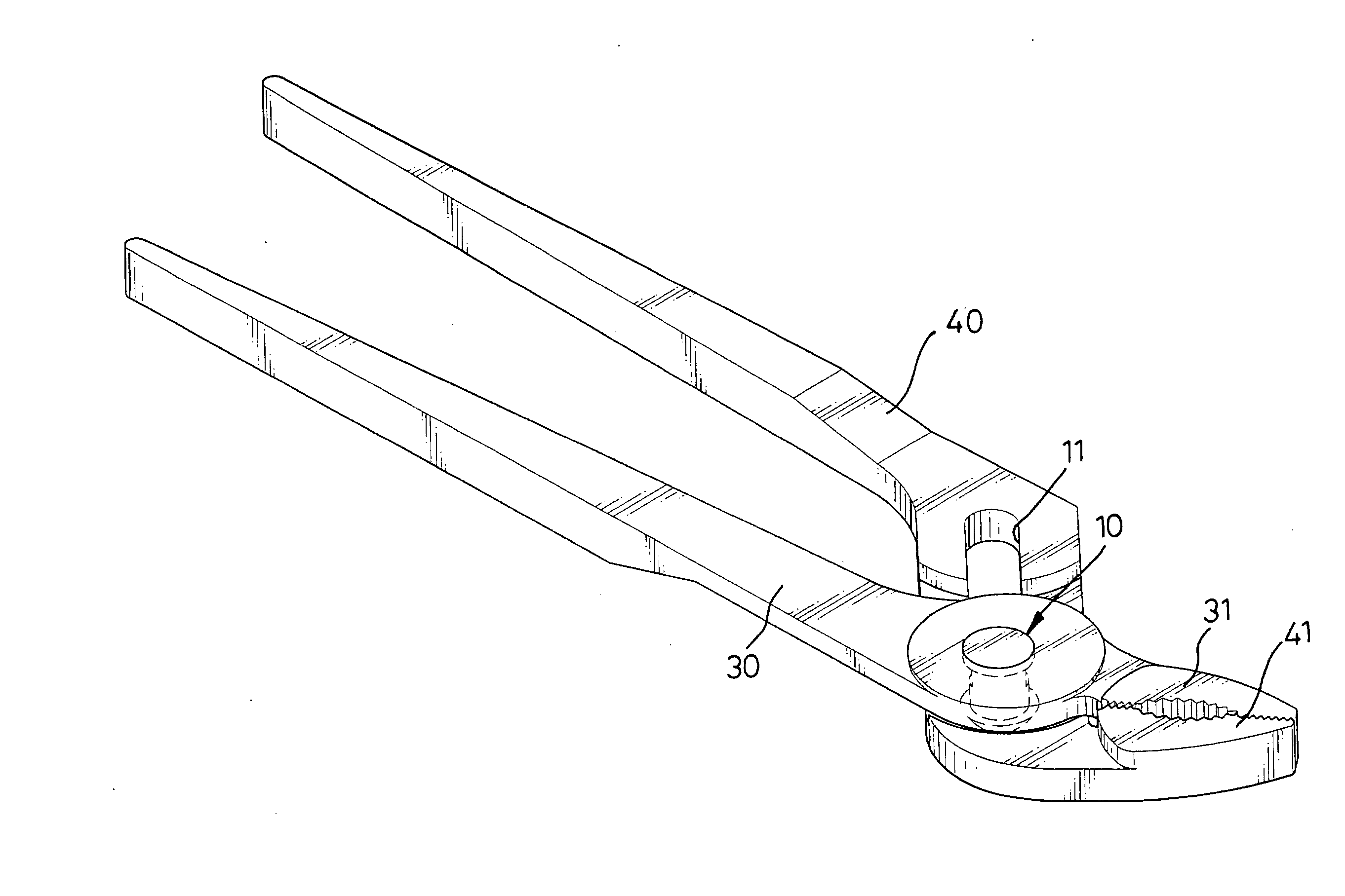
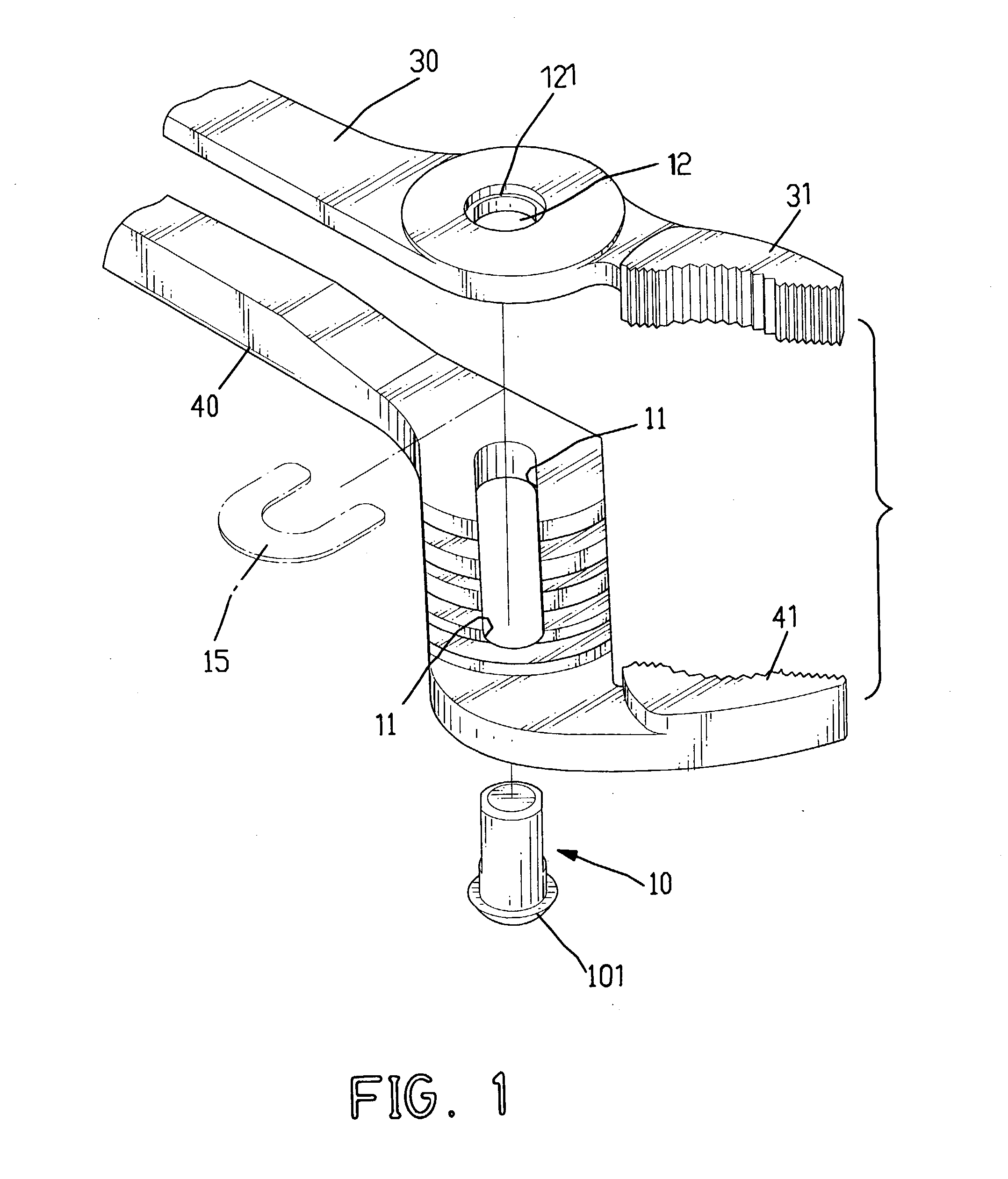
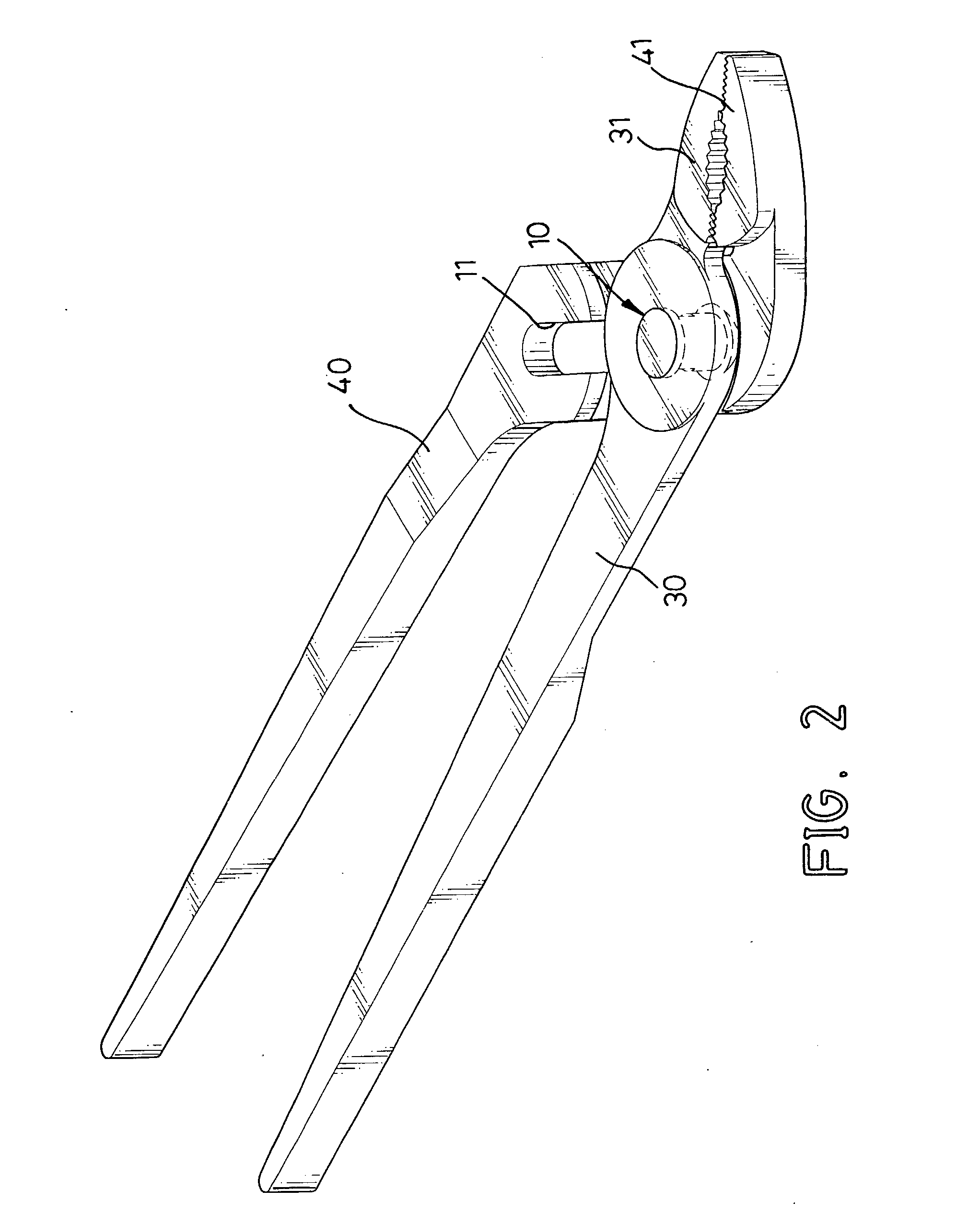
[0016] With reference to FIGS. 1 and 2, a pair of channel-lock pliers (not numbered) has an adjustable handle (30) and a reference handle (40). The adjustable and the reference handles (30, 40) are pivotally connected by a joint (not numbered) in accordance with the present invention at a junction (not numbered). The adjustable handle (30) has a first toothed jaw (31) extending from the junction of the pliers. Similar, the reference handle (40) has a second toothed jaw (41) corresponding to the first toothed jaw (31).

[0017] The adjustable handle (30) and the reference handle (40) have an inside surface (not numbered) that faces the opposite handle and an outside surface (not numbered). The joint comprises a pivot pin (10), an elongated hole (11) and a countersunk pivot hole (12). The pivot pin (10) has a keyed shank (not numbered), a first end (not numbered) and a second end (not numbered). An enlarged head (101) is formed at the first end of the pivot pin (10). The elongated hole (...


PUM


Abstract

A joint of a pair of channel-lock pliers having an adjustable handle and a reference handle that are pivotally connected at a junction includes an elongated hole defined through the reference handle at the junction, a joint hole defined through the adjustable handle at the junction corresponding to the elongated hole and a pivot pin pivotally connecting the adjustable and the reference handles at the junction. The pivot pin has an enlarged first end and a second end, which passes through the elongated hole and the countersunk pivot hole in the handles and extends out of the countersunk pivot hole in the adjustable handle to be pressed and spread to pivotally rivet the handles together and be ground smooth to prevent protruding from the adjustable handle. Consequently, the handles are joined firmly, and appearance of the pliers is nice.

Description

[0001] 1. Field of the Invention[0002] The present invention relates to a joint of a pair of channel-lock pliers, and more particularly to a simple joint of a pair of channel-lock pliers, which operates smoothly.[0003] 2. Description of Related Art[0004] Channel-lock pliers, also called groove joint pliers, are used to grip pipes in plumbing. With reference to FIG. 4, a pair of channel-lock pliers (not numbered) comprises an adjustable handle (30), a reference handle (40) and a conventional joint (not numbered). The adjustable and the reference handles (30, 40) are pivotally connected to each other with the conventional joint at a junction (not numbered). A toothed jaw (41) is formed near the conventional joint on both handles (30, 40). The conventional joint comprises an elongated hole (51), a joint hole (not shown), a bolt (52) and a nut (53). The elongated hole (51) is transversally defined through the reference handle (40) near the toothed jaw (41). The joint hole is defined thr...

Claims


Application Information

Patent Timeline
Patent Type & Authority Applications(United States)
IPC IPC(8): B25B7/06B25B7/10
CPCB25B7/10B25B7/06
Inventor TING, CHENG-CHENG
Owner TING CHENG CHENG
Why Eureka
Try Eureka