Specimen centrifuge apparatus

a centrifuge and specimen technology, applied in the direction of centrifuges, instruments, specific gravity measurement, etc., can solve the problems of consuming energy in vain, requiring a relatively large space for the apparatus to centrifuge a number of specimens at once, and requiring a relatively large spa

Active Publication Date: 2004-09-23
IDS CO LTD
View PDF8 Cites 57 Cited by
  • Summary
  • Abstract
  • Description
  • Claims
  • Application Information

AI Technical Summary

Problems solved by technology

However, the apparatus requires a relatively large space because the first and second rotors need to be arranged together within the same horizontal surface.
It is difficult for the apparatus to centrifuge a number of specimens at once because its centrifuging capacity is limited.
It is therefore likely that energy will be consumed in vain.

Method used


Image

  • Specimen centrifuge apparatus
  • Specimen centrifuge apparatus
  • Specimen centrifuge apparatus

Examples


first embodiment

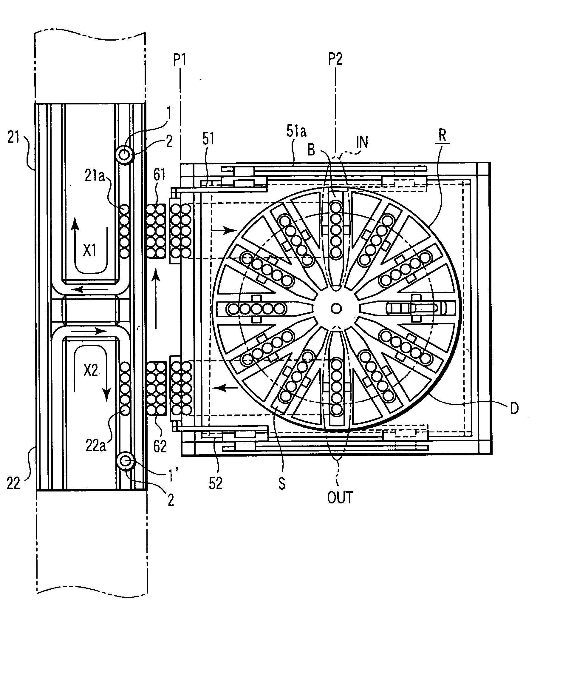
[0024] The rotor R has a plurality of specimen-container buckets B. The buckets B are shakably attached to the circumference of a rotating disc D of the rotor R. Each of the buckets B can store a given number of (five in the first embodiment) specimen containers 1. The rotor R will be described in detail later.

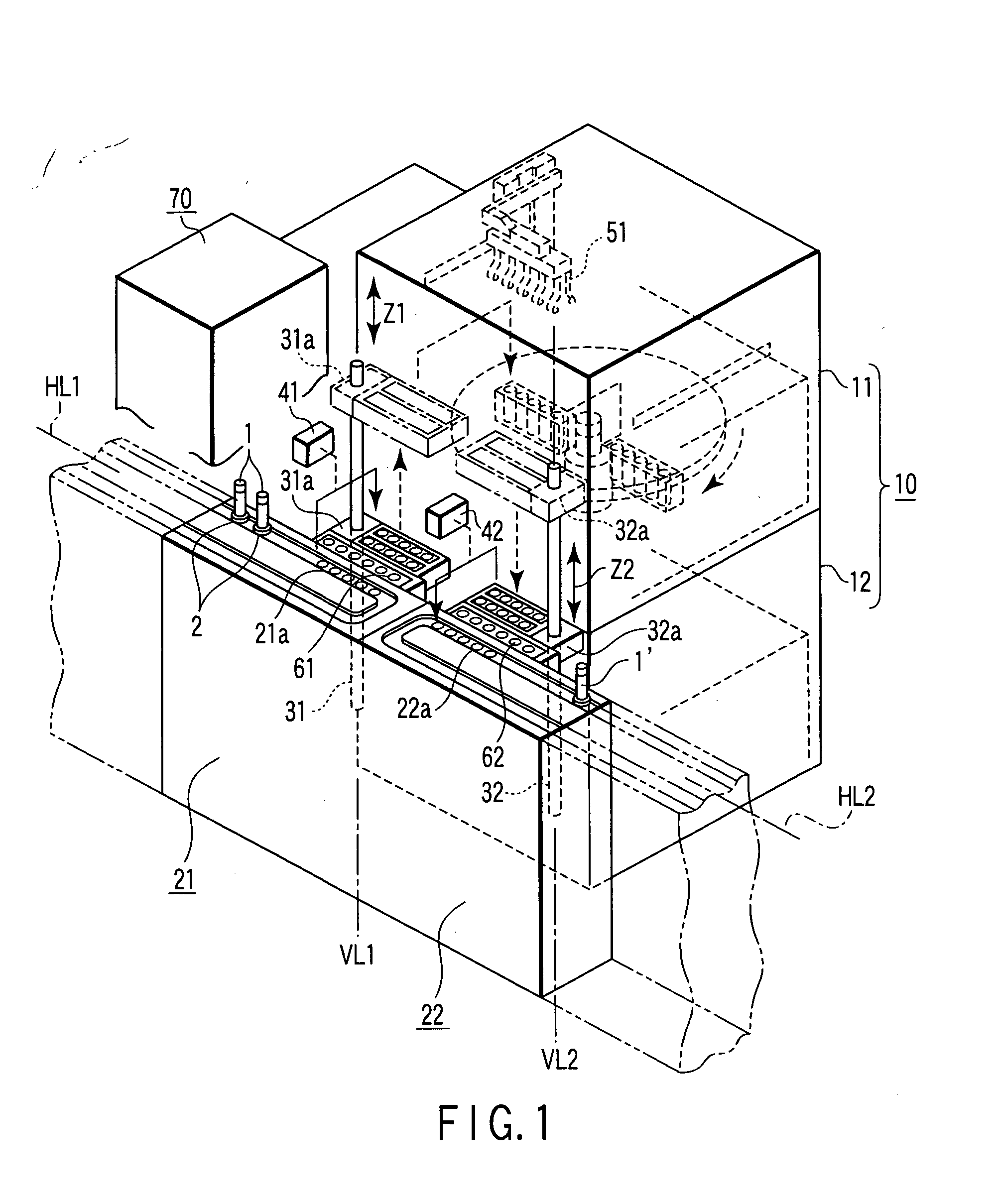
[0025] Each of the cabinets 110 and 120 has an opening (not shown) on its front wall. The specimen containers 1 can be inserted and removed through the opening.

[0026] A carry-in conveyor 21 is provided along a horizontal conveyance line HL1 that passes by the centrifuge device 10. The carry-in conveyor 21 conveys a plurality of pre-processed specimen containers 1 and has a belt-type conveyance lane formed to make a U-turn portion near the centrifuge device 10. The U-turn portion of the belt-type conveyance lane, which is close to the centrifuge device 10, has a container delivering section 21a. Thus, the specimen containers 1 such as test tubes are held by a holder 2 called a ...

second embodiment

[0061] FIG. 7 is a top view of the principal part of a specimen centrifuge apparatus according to a second embodiment of the invention.

[0062] The second embodiment differs from the first embodiment as follows. The carry-in conveyor 21 and carry-out conveyor 22 are arranged in parallel to each other and the centrifuge device 10 is interposed between the conveyors 21 and 22. The locations of container inserting position IN and container removing position OUT on the rotor R are 180 degrees different from each other.

[0063] The second embodiment has the advantage that the conveyance lanes of the carry-in conveyor 21 and carry-out conveyor 22 each have only to be formed straightly. Since the second embodiment is the same as the first embodiment except for the above, its detailed descriptions are omitted.

third embodiment

[0064] FIG. 8 is a top view of the principal part of a specimen centrifuge apparatus according to a third embodiment of the invention.

[0065] The third embodiment differs from the first embodiment as follows. A plurality of (four in the third embodiment) notches K are formed in the circumference of rotating disc DX of rotor RX of centrifuge device 10. Four specimen container buckets BX each shaped like a rectangular parallelepiped are arranged in their respective notches K such that the longitudinal direction of each bucket BX is set toward the tangent to the rotating disc DX.

[0066] The third embodiment also differs from the first embodiment as follows. The locations of carry-in and carry-out conveyors 21 and 22 are 90 degrees different from each other, and the specimen containers are inserted at and removed from the container inserting and removing positions IN and OUT which are spaced each other by 90 degrees on the rotor RX.

[0067] The invention can be applied to a centrifuge devic...


PUM

PropertyMeasurementUnit
timeaaaaaaaaaa
rotation directionsaaaaaaaaaa
energyaaaaaaaaaa

Abstract

A specimen centrifuge apparatus comprises a specimen container carry-in system and a specimen container carry-out system. The specimen container carry-in system has a specimen container carry-in conveyor for loading pre-processed specimen containers into specimen centrifuge units stacked one on another in a centrifuge device, a carry-in elevator, a carry-in transfer arm, and a loading arm. The specimen container carry-out system has a specimen container carry-out conveyor for unloading the processed specimen containers from the specimen centrifuges, a carry-out elevator, a carry-out transfer arm, and an unloading arm.

Description

[0001] This application is based upon and claims the benefit of priority from the prior Japanese Patent Application No. 2003-024062, filed Jan. 31, 2003, the entire contents of which are incorporated herein by reference.[0002] 1. Field of the Invention[0003] The invention relates to a specimen centrifuge apparatus for use in a specimen testing center and the like.[0004] 2. Description of the Related Art[0005] The following specimen centrifuge apparatus is proposed as one for use in a specimen testing center and the like (see Japanese Patent Application KOKAI Publication No. 2000-84436). This apparatus includes first and second rotors. While one of the rotors is centrifuging a specimen, the other rotor replaces a specimen-contained tube with another one.[0006] The above specimen centrifuge apparatus is capable of centrifuging specimens with efficiency. However, the apparatus requires a relatively large space because the first and second rotors need to be arranged together within the ...

Claims


Application Information

Patent Timeline
Patent Type & Authority Applications(United States)
IPC IPC(8): B04B11/00B04B5/02B04B5/04B04B13/00G01N35/00G01N35/02
CPCB04B5/0421B04B13/00B04B2011/046G01N35/025Y10T436/114165B04B5/10Y10T436/113332Y10T436/111666G01N2035/00504
Inventor ITOH, TERUAKI
Owner IDS CO LTD
Why Eureka
Try Eureka