

Portable recyclable fluid flushing method
a portable, recyclable technology, applied in the direction of volume metering, single-unit apparatus, instruments, etc., can solve the problems of limited useable flushing fluid amount, small-scale prior art portable flushing devices used for emergency flushing of eyes, skin or wounds, etc., to achieve convenient manufacture, maintenance and repair, and sufficient small and lightweight
- Summary
- Abstract
- Description
- Claims
- Application Information
AI Technical Summary
Benefits of technology
Problems solved by technology
Method used
Image

Examples
Embodiment Construction
. 1-4--PREFERRED EMBODIMENT
[0198] Flowchart
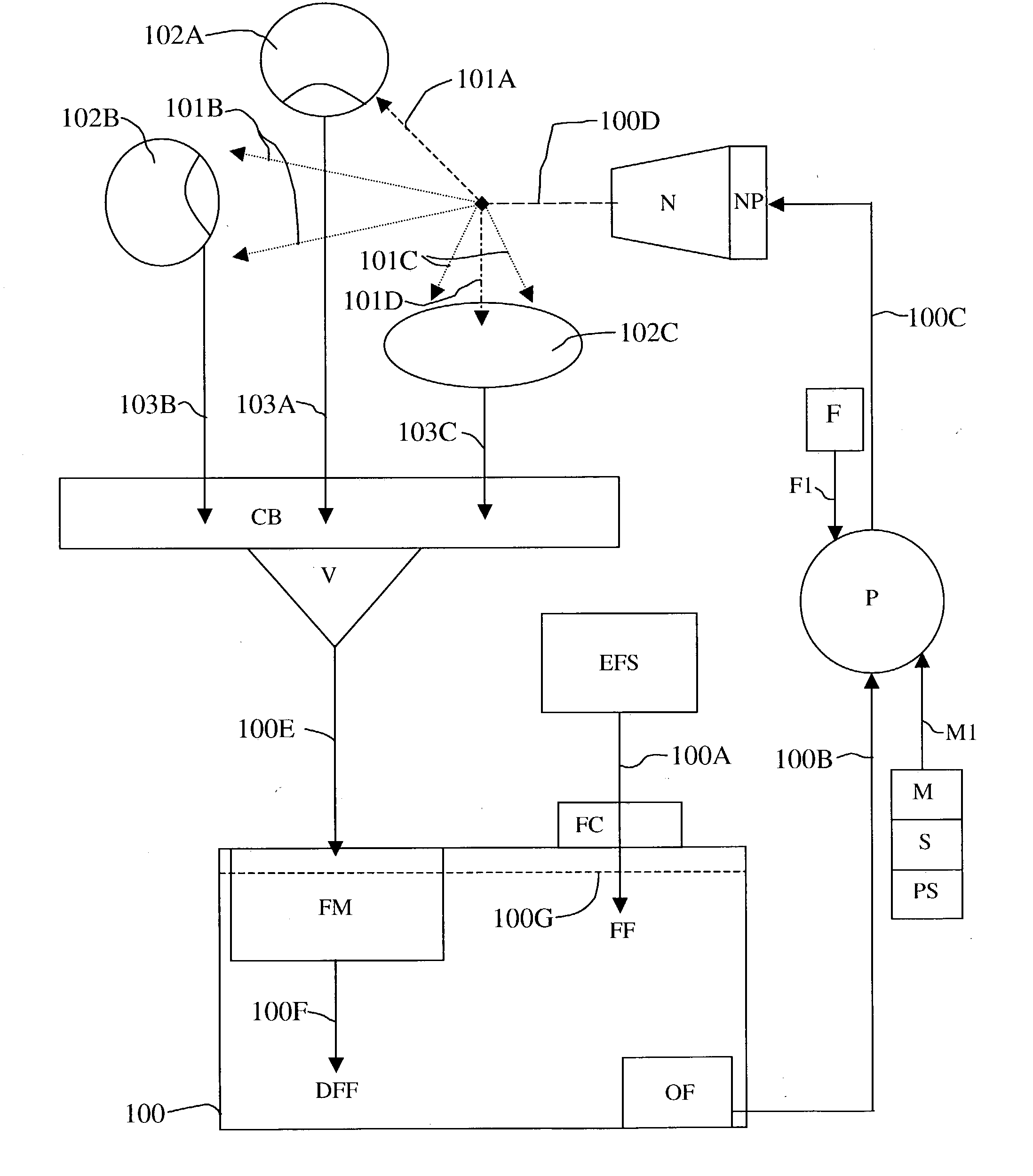
[0199] FIG. 1 shows a diagrammatic flowchart of the fluid transport system within a portable recyclable fluid flushing system done in the method of the present invention of a portable recyclable fluid flushing method. The primary components of the fluid transport system of the portable recyclable fluid flushing method of the invention as shown in FIG. 1 are well known conventional elements of the related prior arts, and therefore require little detailed explanation.
[0200] A plastic or other polymeric material fluid container 100 is filled with an appropriate flushing fluid, represented in the drawing by a boxed-in "FF" (i.e., boxed-in within container 100), typically sterile water or a water-based solution, to a fluid level line 100G from an external fluid supply source, represented in the drawing by a boxed-in "EFS." Fluid travels along a downwardly disposed arrow-line 100A into container 100, when a plastic or other polymeric material, sc...
PUM
 Abstract
Description
Claims
Application Information