Distributed vacuum debris collector

a vacuum and debris collector technology, applied in the field of dust collection, can solve the problems of premature unusable airborne particulates, and affecting the effective capture area of the collector, so as to enhance the capture of airborne particulates, failure of tools, and reduce the effect of aging

Inactive Publication Date: 2010-07-27
NUNKE EDWARD J
View PDF28 Cites 2 Cited by
  • Summary
  • Abstract
  • Description
  • Claims
  • Application Information

AI Technical Summary

Benefits of technology

[0018]A first object of the invention is to provide a low-cost and easy coupling to an existing or custom vacuum source. A second object of the invention is to enable the coupling to be sufficiently compact and lightweight to be portable, while offering mounting options for also fixing the collector in location, depending only upon the particular needs of a user. Another object of the present invention is optimal air flow within an inlet region to enhance the capture of airborne particulates across the entire surface of the collector. A further object of the invention is to increase the effective capture area of the collector sufficiently to enable the collector to be spaced from and physically uncoupled from a particulate generator, thereby permitting free and independent motion of the particulate generator, while ensuring variations in direction of particulate stream will be captured. Yet another object of the present invention is to provide a flow path and couplings which are robust and not easily clogged or impeded.

Problems solved by technology

Exemplary processes are abrasive, such as sanding and grinding operations, though there are other operations as well which release debris into the air.
In addition, there exist a number of additional procedures and processes that do not use power tools, but which also produce undesirable airborne particulates.
Such dust can be inhaled or settle on the skin, causing irritation or constituting a respiratory and / or health hazard for individuals in the immediate vicinity.
Furthermore, such dust can accumulate on tools, causing premature aging and failure of the tools, and on surfaces such as work areas or objects being worked upon, potentially contaminating work areas or disturbing the appearance of the work.
For exemplary purposes, dust produced in an automotive repair shop from grinding, brushing, or other similar processes may foul the air within the shop.
Not only will the shop workers be undesirably exposed to the dust, the automobiles being repaired will likewise be coated with the dust.
As a result, these collectors are found almost exclusively only on “bench” machines which are affixed to the bench or another stand, and are therefore not hand-manipulable except through basic, predetermined movements.
In addition, the prior art has not adequately controlled air flow in these large hoods, resulting in a large portion of the hood being prone to particulates bouncing off of or otherwise escaping from the hood.
These dust collectors suffer from two opposing challenges.
The first challenge arises from the operating speed of the machine or tool.
Unfortunately, this also means that the particles ejected therefrom are ejected at great velocities, and may be entrained in a high velocity air stream produced by the abrasive tool.
Unfortunately, the exact direction of the stream is often dependent upon the angle of contact between tool and work.
The second challenge arises when the tool is portable.
The dust collector necessarily interferes with the portable nature of the tool.
This interference arises from the additional bulk required for the collector, but perhaps more importantly, also arises from a desire for efficiency of collection to couple the collector to a vacuum source.
This additional hosing can greatly interfere with proficient manipulation of the tool.
A small collector is less likely to capture particulate, and, without a hose coupled to a vacuum source, a collection bag or the like blocks flow and rapidly clogs.
Trying to maintain a small, uncoupled dust collector necessarily renders the dust collector substantially less effective than is desirable for most work environments.
These collectors are useful and beneficial, but not adequate for most work environments.
While more universal, these patents suffer from the drawbacks associated with the tool-specific hoods described herein above.

Method used


Image

  • Distributed vacuum debris collector
  • Distributed vacuum debris collector
  • Distributed vacuum debris collector

Examples


Embodiment Construction

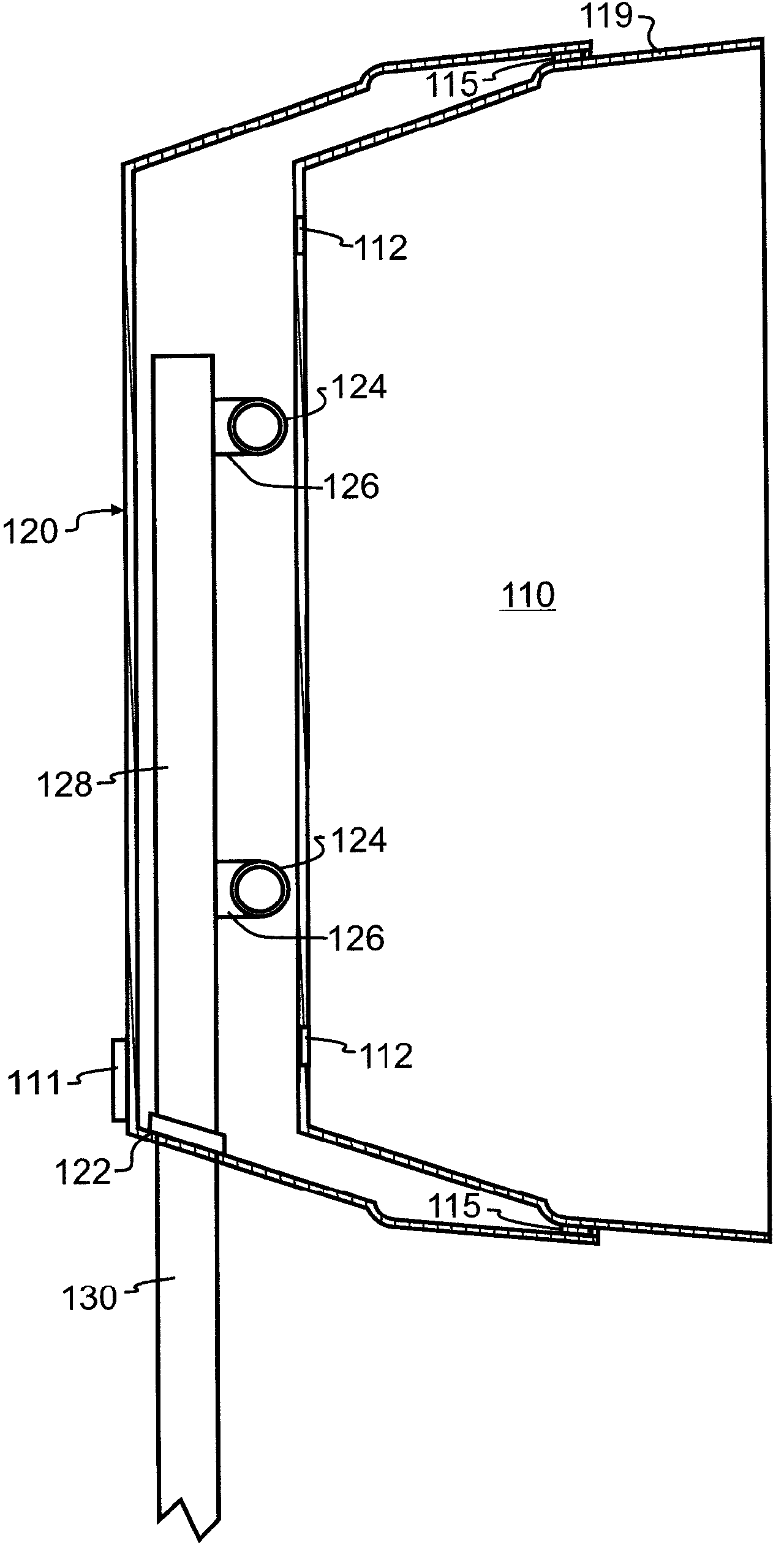
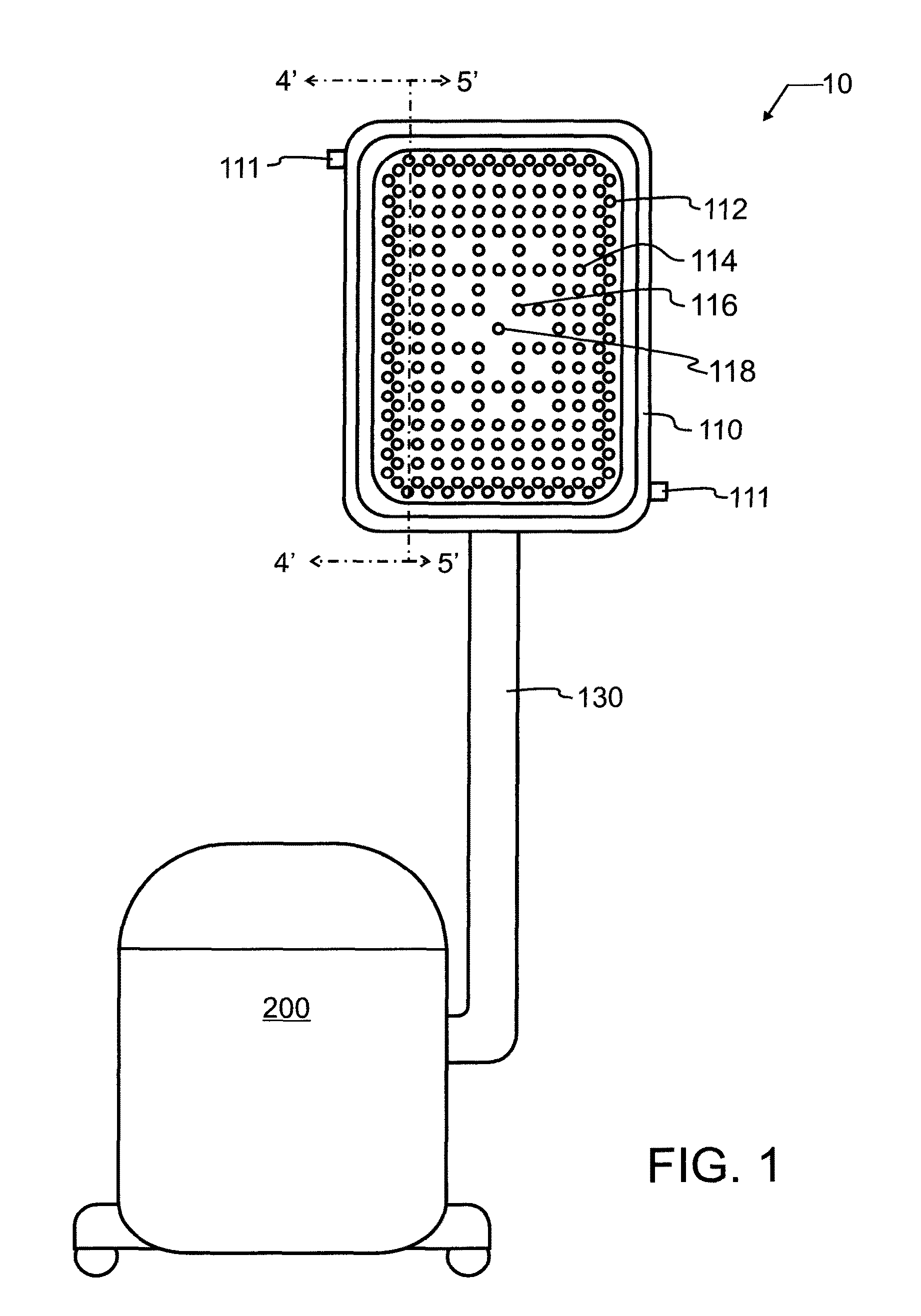
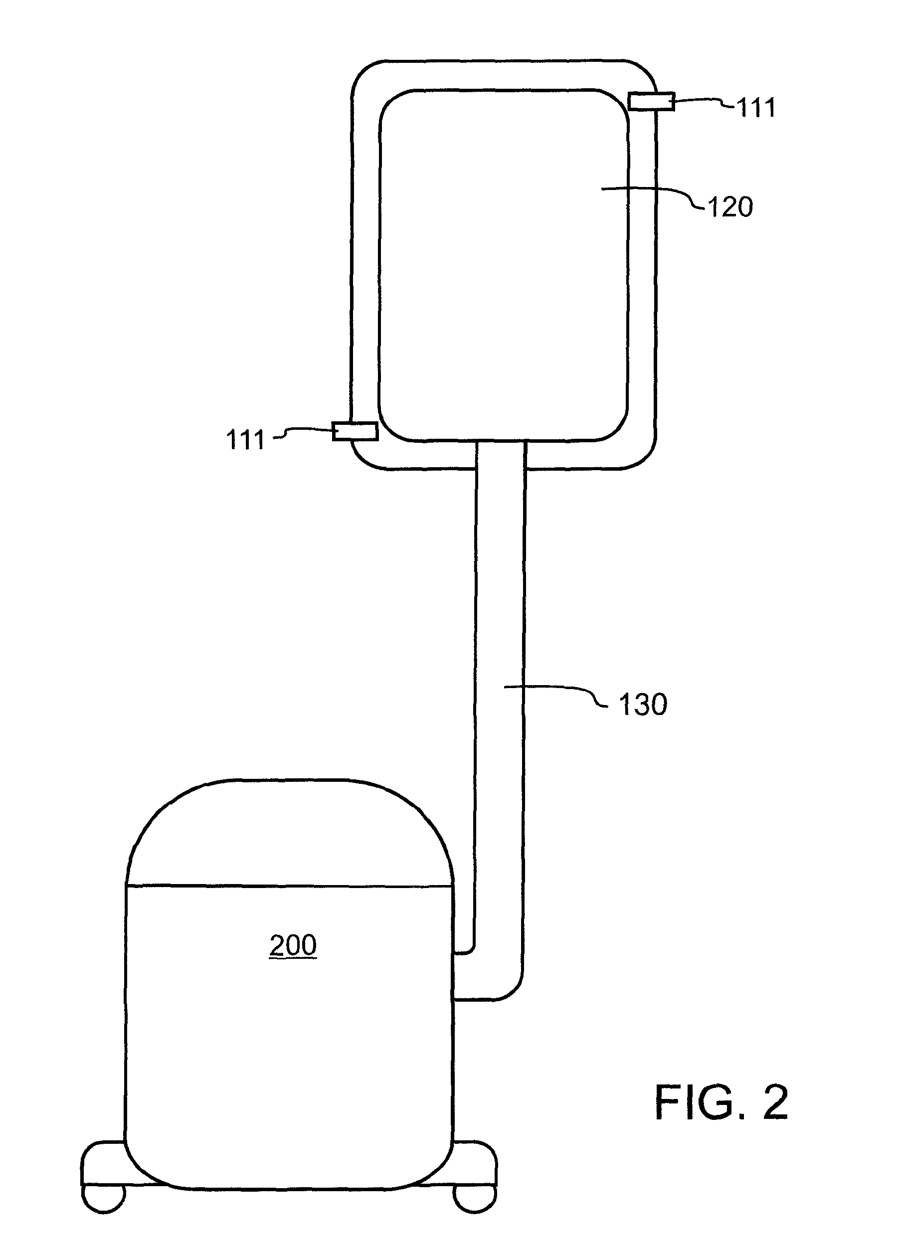
[0032]Manifested in the preferred embodiment, the present invention provides a readily transportable distributed vacuum debris collector 10. In a most preferred embodiment of the invention illustrated in FIGS. 1 and 2, distributed vacuum debris collector 10 is comprised of interlocking containers 110, 120 with inlet suction holes 112, 114, 116, 118 attached to a vacuum or suctioning device 200 via attachment arm 130. Suctioning device 200 may be any suitable source of vacuum or suction, and so for exemplary purposes, but not solely limited thereto, portable vacuum cleaners, central vacuum systems, vacuum fans or blowers, or any other suitable source which will draw sufficient volume and vacuum pressure may be incorporated. While not critical to proper operation, in preferred embodiment distributed vacuum debris collector 10 the attachment arm 130 is rigid, and angled to extend vertically from suctioning device 200. Where suctioning device 200 is a vacuum cleaner, such as a prior art...


PUM

PropertyMeasurementUnit
angleaaaaaaaaaa
densityaaaaaaaaaa
areaaaaaaaaaaa

Abstract

A dust collector has a vacuum coupling for connection to a vacuum source such as a portable vacuum cleaner or other suitable source. A vacuum reservoir is formed from a chamber between nested interlocking receptacles. A variable density pattern of inlet holes through one interlocking container into the vacuum reservoir provides better flow and capture of debris, while multiple inlets within the vacuum reservoir provide even and consistent suction. A variety of inlet geometries are presented that are suitable to a variety of purposes.

Description

BACKGROUND OF THE INVENTION[0001]1. Field of the Invention[0002]This invention pertains generally to the field of debris collection, and more specifically to a collector for airborne debris.[0003]2. Description of the Related Art[0004]Portable power tools greatly facilitate many tasks, including both fabrication and repair. For exemplary purposes, a power hand grinder may be used to remove material or cut through metal in a very small fraction of the time required to complete the same task manually. The particular power source used to power the tool is not important for the present invention, and is known to include such diverse sources as compressed air, electricity, internal combustion engines, and other suitable sources.[0005]These portable power tools have been devised for many tasks, some which are known to rapidly expel large amounts of fine debris into the air. Exemplary processes are abrasive, such as sanding and grinding operations, though there are other operations as well...

Claims


Application Information

Patent Timeline
Patent Type & Authority Patents(United States)
IPC IPC(8): B01D51/00
CPCA47L9/02B01D2279/55
Inventor NUNKE, EDWARD J.
Owner NUNKE EDWARD J
Why Eureka
Try Eureka