
Relocatable habitat unit

a technology of habitat units and housing units, applied in the direction of building components, building types, constructions, etc., to achieve the effect of easy patching of composite materials

Active Publication Date: 2021-10-19
STRATEGIC OPERATIONS INC
View PDF8 Cites 1 Cited by
  • Summary
  • Abstract
  • Description
  • Claims
  • Application Information

AI Technical Summary

Benefits of technology

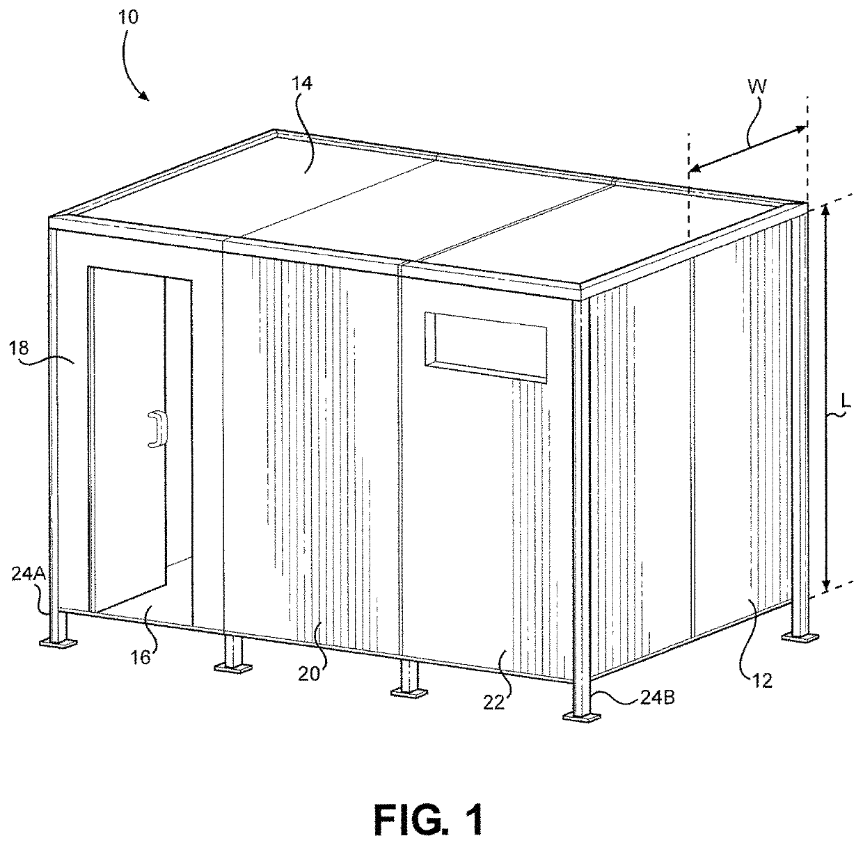
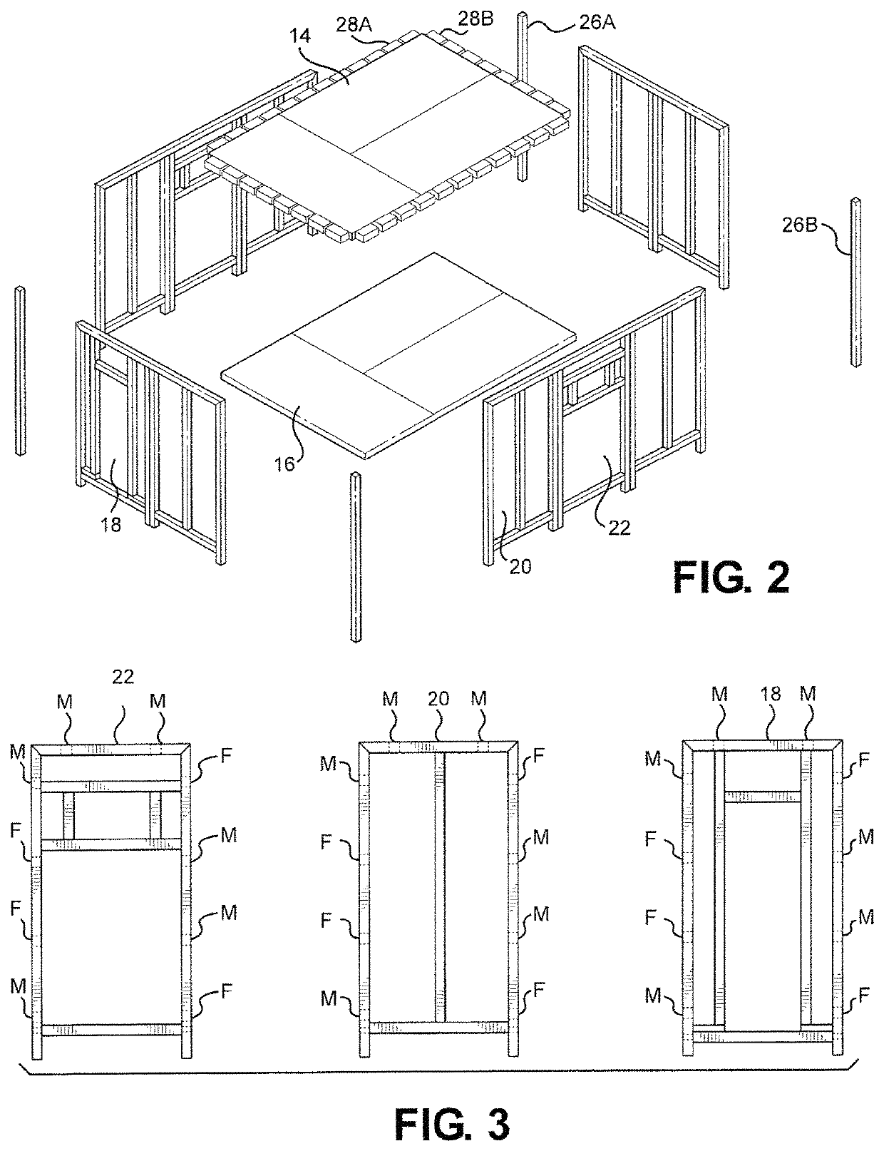
[0012]The RHU is based on a lightweight 4′.times.8′ composite material panel system and engineered to assemble into multi-story, complex configurations with a single tool. The RHU panels are constructed with pultruded fiberglass reinforced plastic beams, bonded with wood, composite, or expanded polystyrene foam panels that are laser cut to replicate the look and texture of various building materials like brick, adobe, mud, wood, bamboo, straw, thatch, etc., sprayed with one-eighth inch of a fire retardant pro-bond and “sceniced” (Pronounced SEE-nicked; a movie industry term that means “aged” to look weathered). Materials and construction provide all-weather, long-lasting, fire-retardant structures suitable for year-round military training in all environments.
[0013]In a preferred embodiment, any interior or exterior panel can be interchanged. Common amenities such as windows, doors, stairs, etc. can be attached or installed to the RHU structure. Additionally, a variation of these modular panels can also be used to clad other structures, such as containers, wooden temporary structures, or permanent buildings. For this assembly operation, each panel includes male (M) and female (F) lock connectors. Specifically, these connectors are located along the periphery of each panel, and of each component that interfaces with the edge of a panel. Importantly, all of the (M) connectors can be engaged with a respective (F) connector using the same tool. Thus, an entire RHU can be assembled and disassembled in this manner. Further, each panel is sufficiently lightweight in order to be moved and positioned by one person. As a practical matter, a second person may be required to use the tool and activate the connectors as a panel is being held in place by the other person.
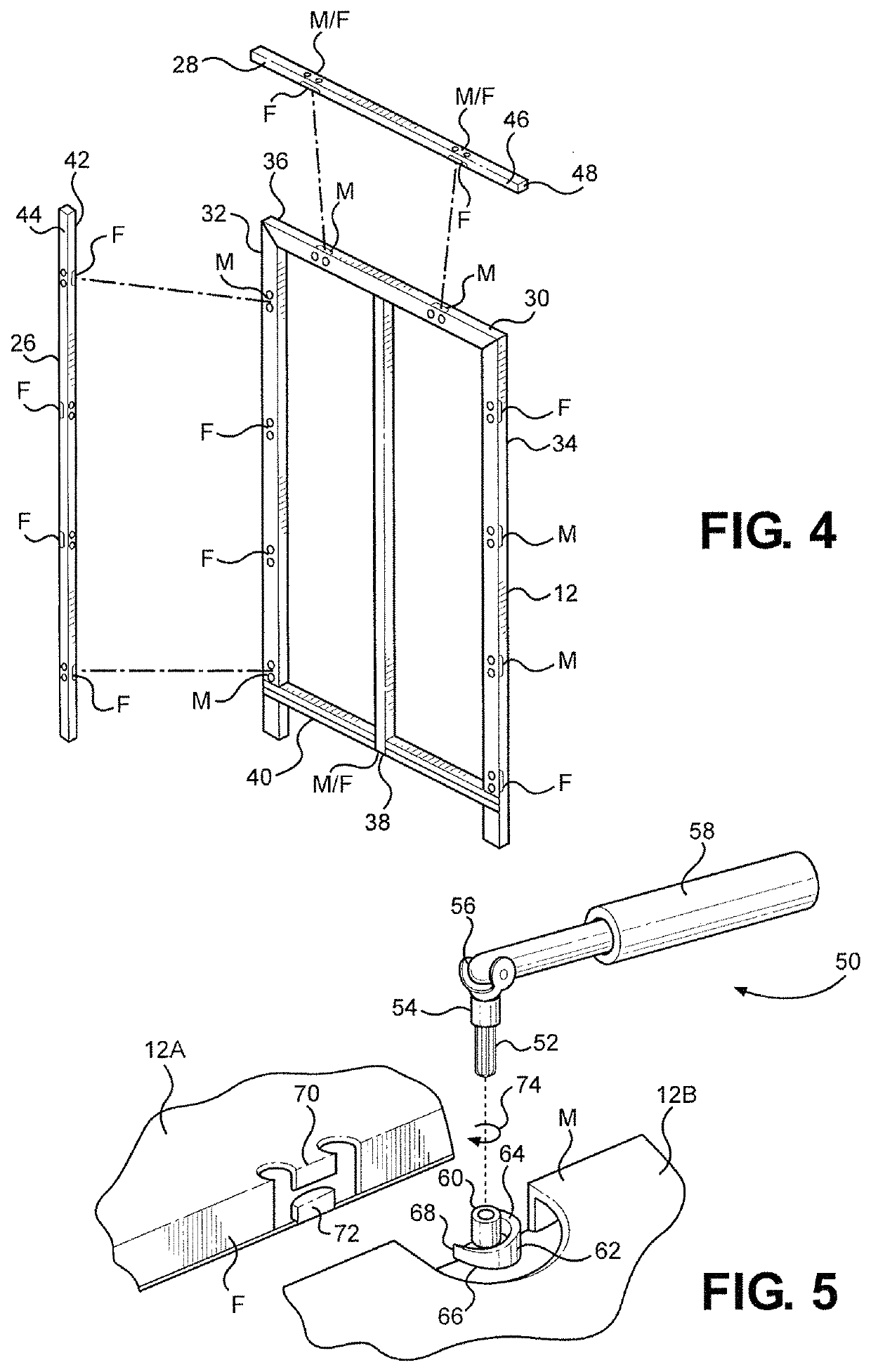
[0016]The placement and location of male (M) and female (F) lock connectors on various panels of the construction set is important. Specifically, in one embodiment, along the right side edge of each wall panel, between its top edge and bottom edge, the lock configuration is (FMMF). Along its left side edge, the lock configuration is (MFFM). Further, along the top edge the lock configuration is (MM), and along the bottom edge it is (M) or (F), depending on the connector of the floor panel. Each lock sequence will have a complementary analogue on the interfacing surface allowing easy interchangeability of the panels.
[0019]In a preferred embodiment all panels are interchangeable. A frame is constructed consisting of vertical corner posts and horizontal beams (analogous to the corner connections and ceiling attachments), each formed with M and F lock connectors along their length that complement the lock connectors on the panels. Once the frame is in place, the panels may be configured and reconfigured as needed. Vertical corner posts and horizontal beams are also secured together using the single tool and additional hardware. By assembling a plurality of RHUs in this manner, the RHUs can be configured in any complex configuration that will best simulate the indigenous environment desired. A plurality of RHUs can be placed side-to-side, back-to-back, offset, stacked, or staggered to create a multi-level scalable structure. A simple repair kit provides quick easy patching of the composite materials.

Problems solved by technology

Further, each panel is sufficiently lightweight in order to be moved and positioned by one person.

Method used


Image

  • Relocatable habitat unit
  • Relocatable habitat unit
  • Relocatable habitat unit

Examples


Embodiment Construction

[0064]Referring initially to FIG. 1, a Relocatable Habitat Unit (RHU) in accordance with the present disclosure is shown and is generally designated 10. As shown, the RHU 10 includes a plurality of individual panels, of which the generic panel 12 (sometimes hereinafter referred to as a wall panel) is 15 exemplary. The panel 12 is substantially flat, and is rectangular in shape with a width (“W”) of approximately four feet and a length (“L”) of approximately eight feet (i.e. the panel 12 is a 4.times.8). Alternatively, a panel 12 may be dimensioned as a 4.times.4. The depth of the panel 12 can vary slightly but, in general, will only be two or three inches. Preferably, the panel 12 is made of a light-weight composite polymer foam type material, such as expanded polystyrene foam panels having a density of approximately two pounds per cubic foot, with pultruded fiberglass reinforced plastic beams framing the foam core.

[0065]In an embodiment of the RHU 10 of the present disclosure there...


PUM

PropertyMeasurementUnit
elevationaaaaaaaaaa
lengthaaaaaaaaaa
lengthaaaaaaaaaa

Abstract

A field-deployable construction set for the assembly of a Relocatable Habitat Unit (RHU), used for simulating real world environments without costly construction expenses. The various panels, supports, and accessories used to construct an RHU include male (M) and female (F) lock connectors located on their respective peripheries and a frame constructed from a plurality vertical corner posts and horizontal beams provide the user with innumerable options for floor plans and building design, further providing significant options for reconfiguration of floor, ceiling, and wall panels without having to disassemble the structure. The exterior composition of the expanded polymer foam is customizable to provide a realistic environment for high quality training in a versatile system that is deployable by truck or aircraft and can be assembled with only a single tool.

Description

CROSS-REFERENCE TO RELATED APPLICATIONS[0001]This application is a continuation-in-part of and claims the benefit of priority to U.S. patent application Ser. No. 16 / 000,394, filed Jun. 5, 2018 and entitled “Relocatable Habitat Unit”.[0002]U.S. patent application Ser. No. 16 / 000,394 is a continuation-in-part of and claims the benefit of priority to U.S. patent application Ser. No. 14 / 881,440, filed Oct. 13, 2015, entitled “Relocatable Habitat Unit”, and issued as U.S. Pat. No. 9,988,806 on Jun. 5, 2018; which is a continuation of and claims the benefit of priority to U.S. patent application Ser. No. 14 / 217,216, filed Mar. 17, 2014, entitled “Relocatable Habitat Unit”, and issued as U.S. Pat. No. 9,157,249 on Oct. 13, 2015; which claims the benefit of priority to U.S. provisional patent application No. 61 / 800,838, filed Mar. 15, 2013 and entitled “Relocatable Habitat Unit”, the contents of all which are incorporated herein by reference in their entirety.[0003]U.S. patent application S...

Claims


Application Information

Patent Timeline
Patent Type & Authority Patents(United States)
IPC IPC(8): E04B1/02E04B1/61E04C2/30E04B1/343E04H1/12E04C2/00E04B1/00
CPCE04B1/34321E04B1/02E04B1/343E04B1/34384E04B1/61E04C2/30E04H1/1205E04B1/00E04B2001/34389E04C2002/001E04B1/34326E04B1/6183E04H1/005E04H1/04E04C2/205E04C2/386E04C2/384E04B1/34317
Inventor SEGALL, STUART C.
Owner STRATEGIC OPERATIONS INC
Learn More