
Optical apparatus for tracking a magnetic tape

Inactive Publication Date: 2006-12-12
QUANTUM CORP
View PDF1 Cites 2 Cited by
  • Summary
  • Abstract
  • Description
  • Claims
  • Application Information

AI Technical Summary

Benefits of technology

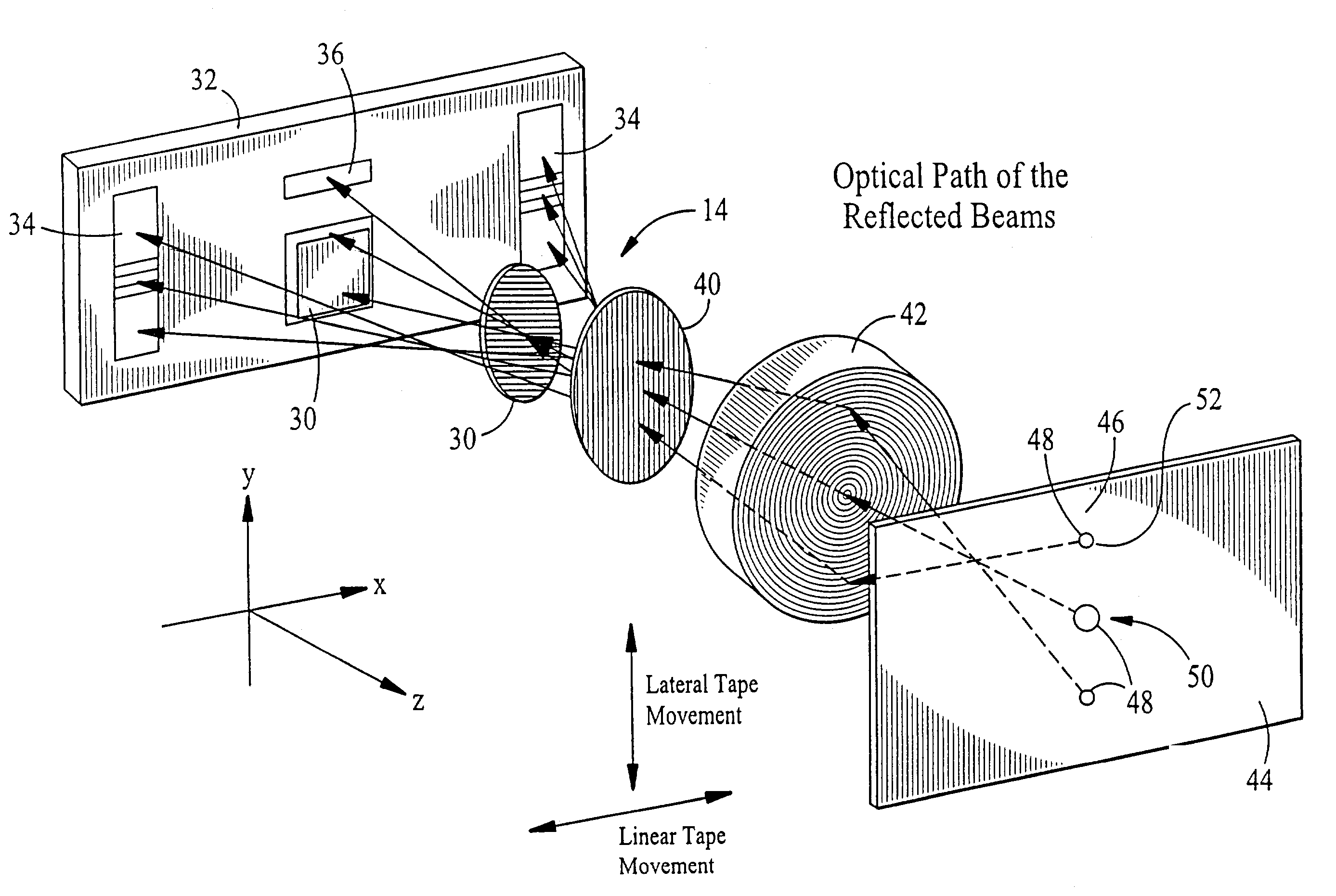
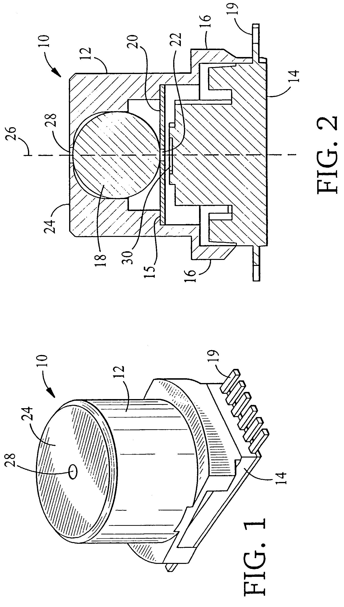
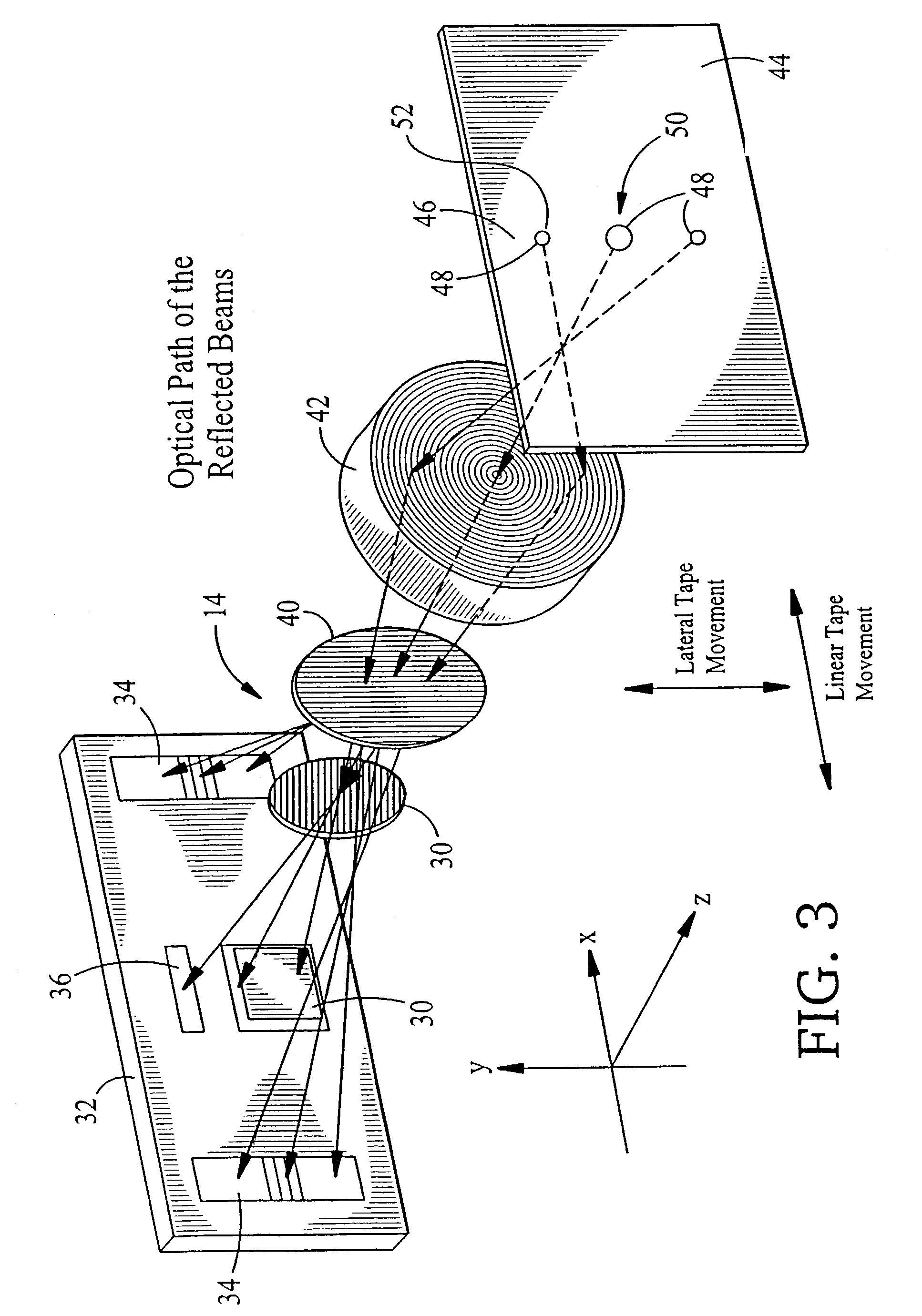
[0010]The systems and methods described herein provide optical servo heads that employ a focusing assembly with reduced complexity, a short focal length and which are sufficiently compact and lightweight to be employed with a servo mechanism that operates to move the optical servo head in real-time. Additionally, the employment of a spherical lens eliminates the need to carefully align conventional lens elements, and thereby reduces the cost of manufacturing.

Problems solved by technology

Because of relatively high linear tape velocity, and because tape substrates continue to be made progressively thinner, guiding tape past a tape head structure along an accurate invariant linear path has proven to be difficult problematical.
One error phenomena is known as “lateral tape motion” or “LTM.” LTM is a major source of tracking errors in linear tape recording.
Unfortunately, a limiting factor is LTM, and at some track width dimension and track density, it is not possible to follow the tape accurately enough to provide reliable performance.
Although these multiple component optical assemblies can work well, they often require the optical pick up head to have a focal length that is too long to allow for employment with a magnetic recording head, which benefits from close proximity to the magnetic recording media.
Additionally, these multi-component lens assemblies can add to the weight of the optical pick up head, which is undesirable in an application where the pick up head is to be moved in real time with the changing position of a servo track.
Additionally, the lens assemblies can add to the expense of manufacture, requiring careful alignment of the lens components to provide an optical path and focal point of desired parameters.

Method used


Image

  • Optical apparatus for tracking a magnetic tape
  • Optical apparatus for tracking a magnetic tape
  • Optical apparatus for tracking a magnetic tape

Examples


Embodiment Construction

[0019]To provide an overall understanding of the invention, certain illustrative embodiments will now be described, including an optical servo head for tracking an optical servo track formed on a magnetic tape. However, it will be understood by one of ordinary skill in the art that the optical servo heads described herein can be adapted and modified to provide systems that can act as servo heads for monitoring tracks on other media, including CD ROMs, floppy disks, hard disk platters, or for any other suitable application. Other additions and modifications can be made to the invention without departing from the scope hereof.

[0020]FIG. 1 depicts one embodiment of an optical servo head for tracking an optically manifested servo track. As shown in FIG. 1 the system 10 includes a housing 12, a semiconductor device 14 mounted to the housing 12, and a sidewall 24 formed at one end of the housing 12 and having an aperture 28 extending therethrough. The depicted optical servo head 10 is suf...


PUM


Abstract

An optical tracking system is presented which aligns a recording head with a magnetic tape. The system relies on an optically detectable servo track on the back of the tape. The servo track is formed by repeatedly engraving, at spaced intervals, three co-linear marks perpendicular to the length of the tape. Laser light reflects off the marks, and passes through a ball lens that directs the reflected light on to separate light detectors, one for each mark. By recording characteristics of the reflected light, the detectors transmit information to the system that permits the recording head to be properly aligned with the tape.

Description

REFERENCE TO RELATED APPLICATION[0001]The present invention is related to commonly assigned, co-pending U.S. patent application Ser. No. 09 / 046,723, entitled “Multi-Channel Magnetic Tape System Having Optical Tracking Servo”, and filed 24 Mar. 1998, the disclosure thereof being incorporated herein by reference.FIELD OF THE INVENTION[0002]The invention relates to systems and methods for tracking movement of a magnetic tape, and more specifically, to optical servo head assemblies that can transmit and receive light patterns suitable for monitoring an optical servo track carried on a magnetic tape to sense and detect lateral movement of the tape.BACKGROUND OF THE INVENTION[0003]Digital tape-recording remains a viable solution for storage of massive amounts of data. Conventionally, at least two approaches are employed for recording of digital information onto magnetic recording tape. One approach calls for moving the tape past a rotating head structure which records and plays back user ...

Claims


Application Information

Patent Timeline
IPC IPC(8): G11B5/584
CPCG11B5/584
Inventor SALIBA, GEORGE A.CHEN, HONGPANISH, JOSEPHCAPPABIANCA, LEOGULBANKIAN, RICHARD
Owner QUANTUM CORP
Learn More