Knee-protecting airbag device

Active Publication Date: 2004-12-30
TOYODA GOSEI CO LTD
View PDF3 Cites 23 Cited by
  • Summary
  • Abstract
  • Description
  • Claims
  • Application Information

AI Technical Summary

Benefits of technology

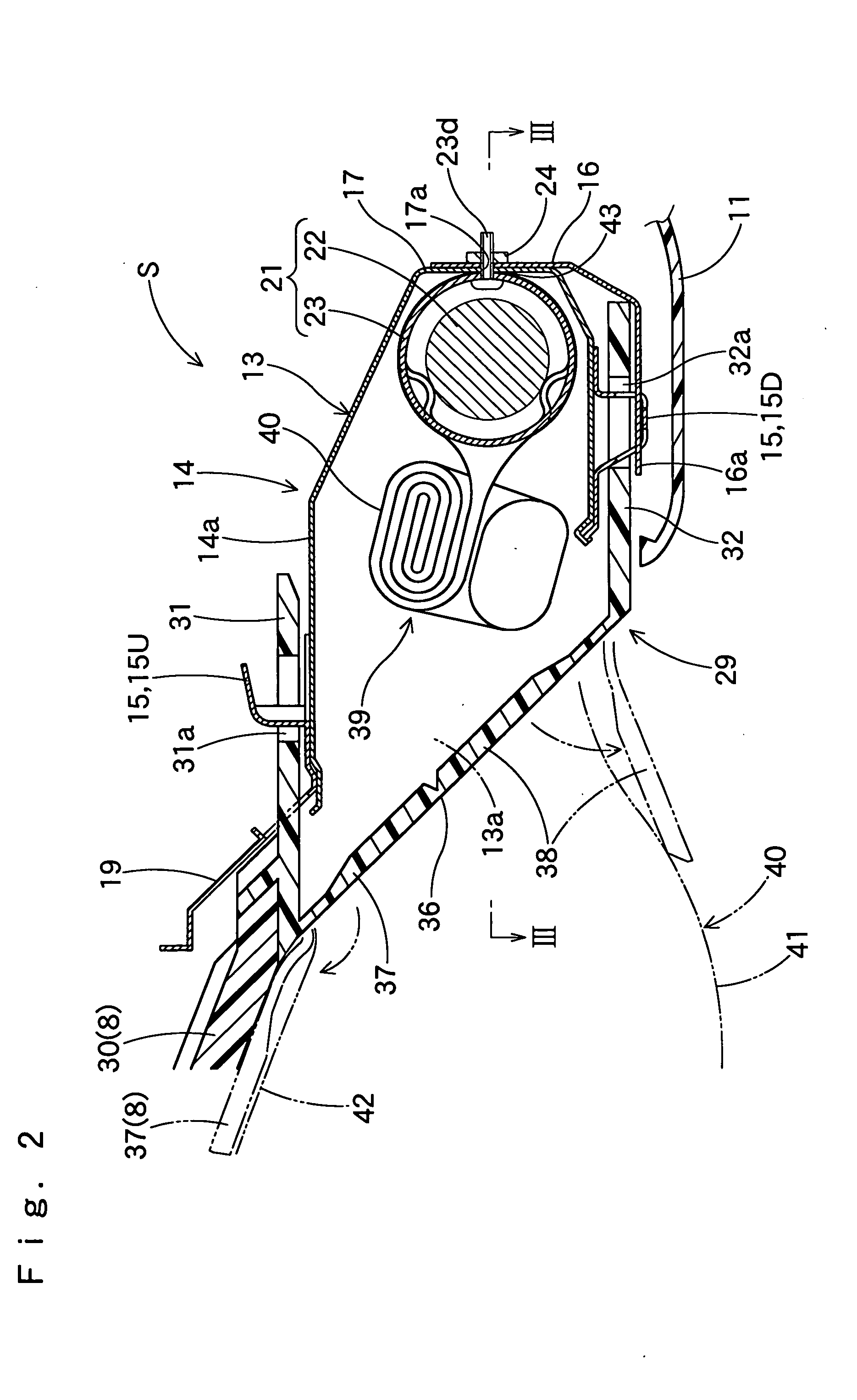
[0021] When the knee-protecting airbag device of the present invention is actuated, the airbag fed with inflation gas protrudes rearward from the housing, and expands while going up. While the airbag unfolds its roll-folding in the transverse folding, the protecting cloth also unfolds together with the upper edge of the airbag body. Since the upper end of the protecting cloth is a free end, the upper end is released from the retainer cloth and rises in advance of the upper end (upper edge) of the airbag body, so that the protecting cloth covers key accessories from the lower side to the back side, and may further wrap the accessories.
[0022] Accordingly, even when the airbag body approaches the key accessories thereafter, the airbag body is able to complete deployment smoothly, since the protecting cloth is interposed between the airbag body and accessories, and protects the airbag body.
[0025] In the knee-protecting airbag device of the present invention, therefore, the airbag body is able to complete deployment and protect the knees of driver securely since the airbag body is protected by the protecting cloth, even if the deploying airbag contacts with accessories connected to a key. Especially, even if the airbag deploys in a narrow space between a driver and a member of the column cover, the protecting cloth is able to cover the lower side or the back side of the key accessories securely, which enables the completely deployed airbag body to protect the knees of the driver securely.
[0027] With this arrangement, when the airbag body unrolls, the folded upper end part of the protecting cloth put on the upper edge portion of the airbag body is easily sprung up by the upper edge portion of the airbag body. Consequently, the protecting cloth is able to cover the back side of key accessories in a wide area up to the upper side, and the contact of the airbag body with key accessories is further prevented.
[0028] In the above case, moreover, it is desired that the upper end part of the protecting cloth is roll-folded toward the airbag body in a condition that the protecting cloth is flatly expanded together with the airbag body, when folded toward the lower end of the protecting cloth, and then is put on the folded upper edge portion of the airbag body. With this arrangement, even if the folded upper end part of the protecting cloth contacts with key accessories when sprung up and unrolling along with the unfolding of the upper edge portion of the airbag body, the upper end part of the protecting cloth is able to unroll smoothly while contacting with accessories, so that the protecting cloth is able to cover the back side of key accessories securely.
[0030] It will also be appreciated that the retainer cloth is elongate enough to cover up to the upper edge of the airbag body when the airbag body and the retainer cloth are both flatly expanded. With this arrangement, upon deployment of the airbag body, even if the driver's side wall of the airbag body nearly contacts with key accessories after the protecting cloth is expanded but before covers the back side of accessories, the retainer cloth is able to protect the airbag body and prevents the same from contacting with the accessories, since the retainer cloth is located up to the upper end of the driver's side wall.

Problems solved by technology

However, since there are various kinds of key accessories such as a spare key, the lower ends of the accessories may contact an inflated part of the airbag and damage the airbag, when the airbag deploys.
Then the protecting cloth may not be able to spring up prior to the airbag body, and therefore, may not be able to cover the lower side or the back side of key accessories.

Method used


Image

  • Knee-protecting airbag device
  • Knee-protecting airbag device
  • Knee-protecting airbag device

Examples


Embodiment Construction

[0046] Preferred embodiments of the present invention are now described below with reference to the accompanying drawings. However, the invention is not limited to the embodiments disclosed herein. All modifications within the appended claims and equivalents relative thereto are intended to be encompassed in the scope of the claims.

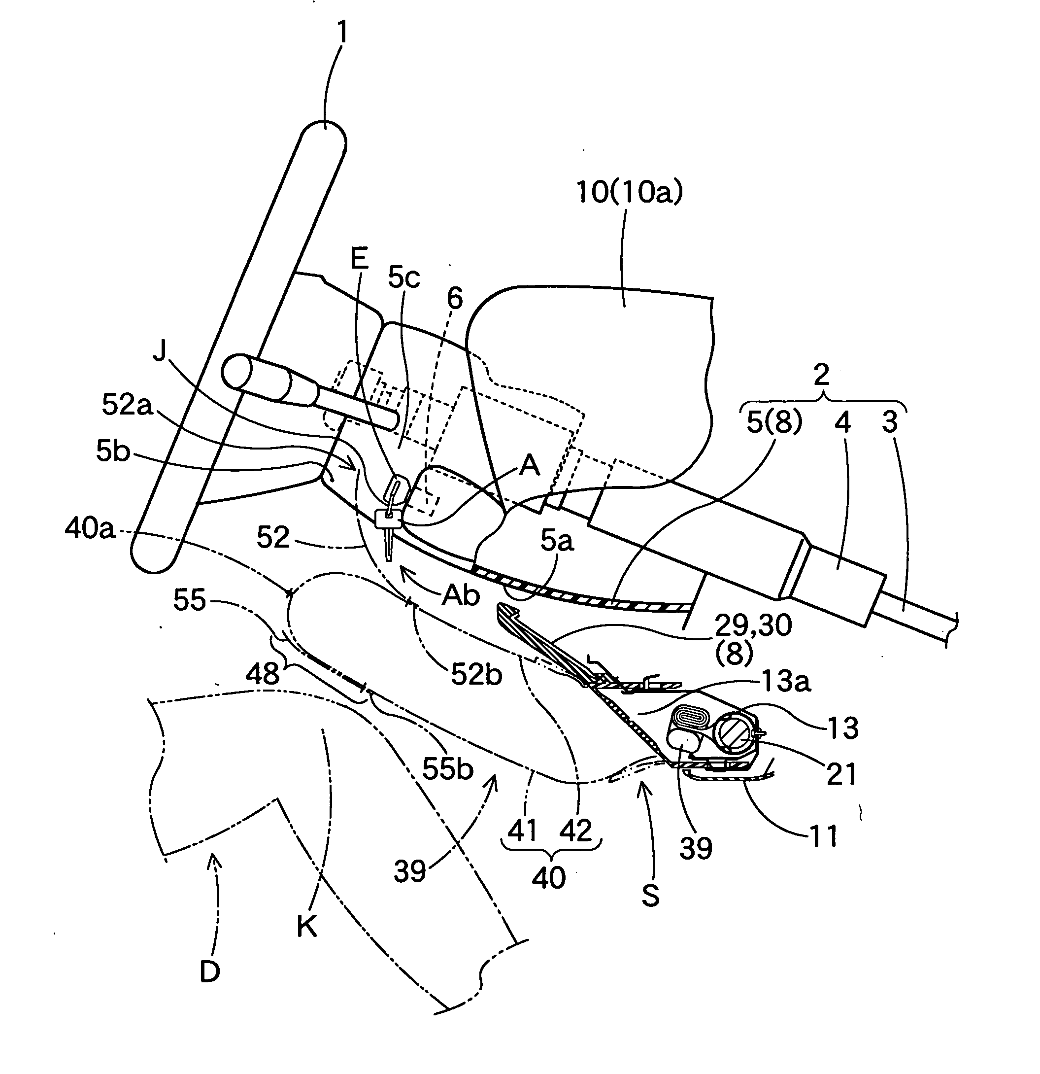
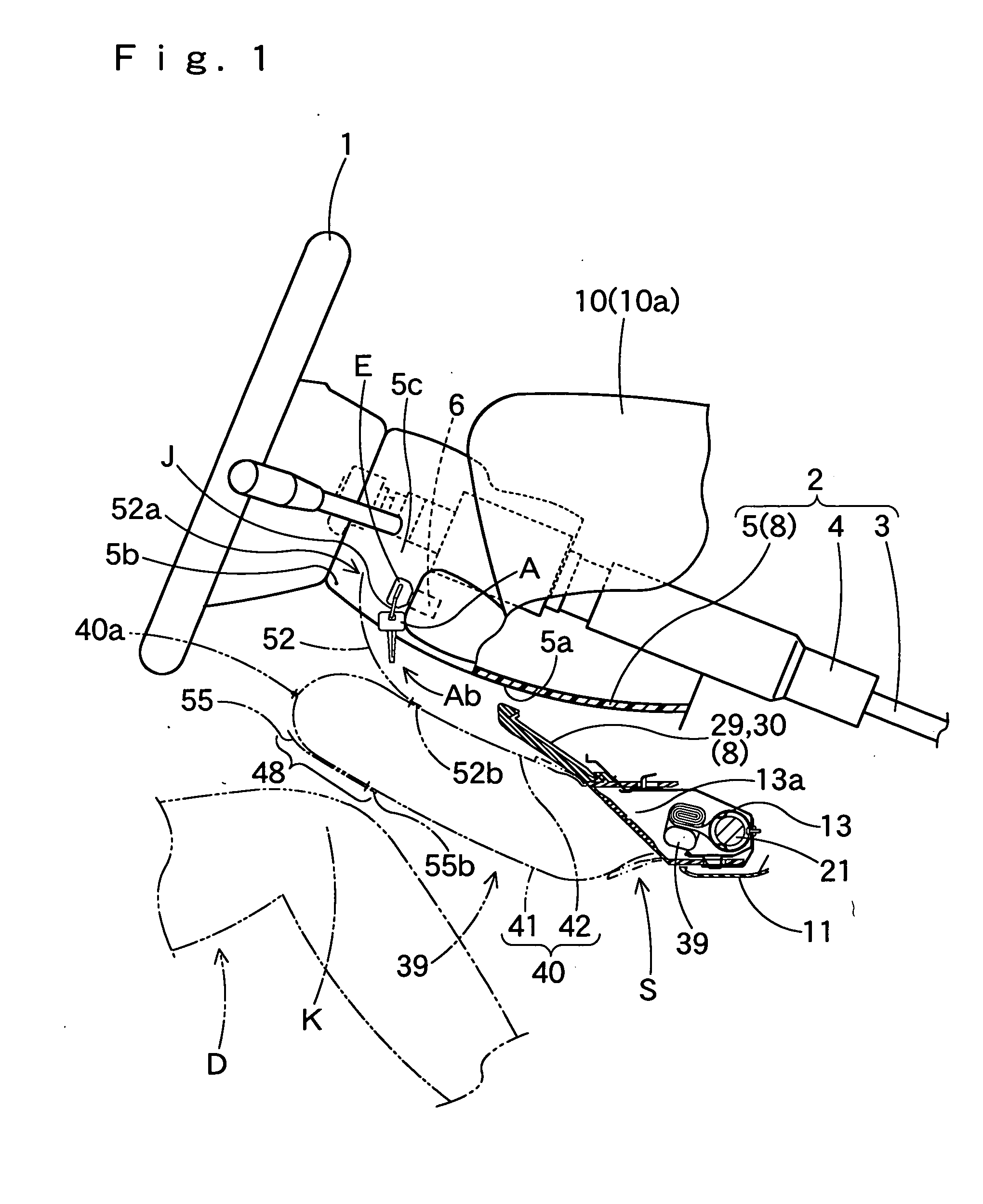
[0047] It is shown in FIGS. 1 and 10 that a knee-protecting airbag device S is located below the steering column 2 and in front of a driver D for protecting knees K of the driver D.

[0048] Up-down, front-rear, and left-right in this specification are based on a state in which the airbag device S is mounted on the vehicle, and therefore, correspond to up-down, front-rear, and left-right of the vehicle with the airbag device mounted thereon.

[0049] Referring to FIG. 1, the steering column 2 includes a main shaft 3 connected to a steering wheel 1, a column tube 4 for covering the main shaft 3, and a column cover 5 for covering those members.

[0050] The column c...


PUM


Abstract

An airbag of the knee-protecting airbag device according to the present invention includes a cover area which covers the lower side or the back side of key accessories and is contactable with the accessories. The airbag includes a bag-shaped airbag body with a driver's side wall and a column side wall, a protecting cloth, and a retainer cloth. The protecting cloth is joined at its lower end to an area in the column side wall below the cover area, while leaving its upper end as free end. The retainer cloth is so joined at its lower end to the driver's side wall as to be capable of covering the upper end part of the protecting cloth as extended to the driver's side wall. The airbag is transversely folded and housed in the housing in a condition that the upper end part of the protecting cloth is extended to the driver's side wall and then the retainer cloth is superposed thereon.

Description

[0001] The present application claims priority from Japanese Patent Application No. 2003-145348 of Mizuno et al., filed on May 22, 2003, the entirety of which is hereby incorporated into the present application by reference.[0002] 1. Field of the Invention[0003] The present invention relates to a knee-protecting airbag device which protects knees of a driver by an airbag expanding and inflating with inflation gas.[0004] 2. Description of the Related Art[0005] In a conventional knee-protecting airbag device for protecting knees of a driver disclosed in WO 02 / 04261 A1, for example, a folded airbag is housed in and held by a housing located in front of the driver. Upon inflow of inflation gas, the airbag rises along the lower surface of a steering column, and deploys for protecting driver's knees. The airbag as completely deployed is provided, in the vicinity of left or right corner in its upper edge, with a cover area for covering the lower side or back side of key accessories of a ke...

Claims


Application Information

Patent Timeline
IPC IPC(8): B60R21/16B60R21/203B60R21/20B60R21/206B60R21/215B60R21/2165B60R21/217B60R21/231B60R21/233B60R21/237
CPCB60R21/203B60R21/206B60R21/2165B60R21/2171B60R21/237B60R2021/23169B60R2021/23324
Inventor MIZUNO, YOSHIOYABUSAKI, HIROMIOHNO, YOSHIKAZU
Owner TOYODA GOSEI CO LTD
Why Eureka
Try Eureka