System and method for bending strip material to create cutting dies

a technology of cutting dies and strips, applied in the direction of metal-working equipment, metal-working tools, metal-working tools, etc., can solve the problem that the method is often no longer economically viabl

Inactive Publication Date: 2005-01-13
SCOTT WESLEY +3
View PDF23 Cites 9 Cited by
  • Summary
  • Abstract
  • Description
  • Claims
  • Application Information

AI Technical Summary

Problems solved by technology

Due to increased labour costs such a method is often no longer economically viable.

Method used


Image

  • System and method for bending strip material to create cutting dies
  • System and method for bending strip material to create cutting dies
  • System and method for bending strip material to create cutting dies

Examples


Embodiment Construction

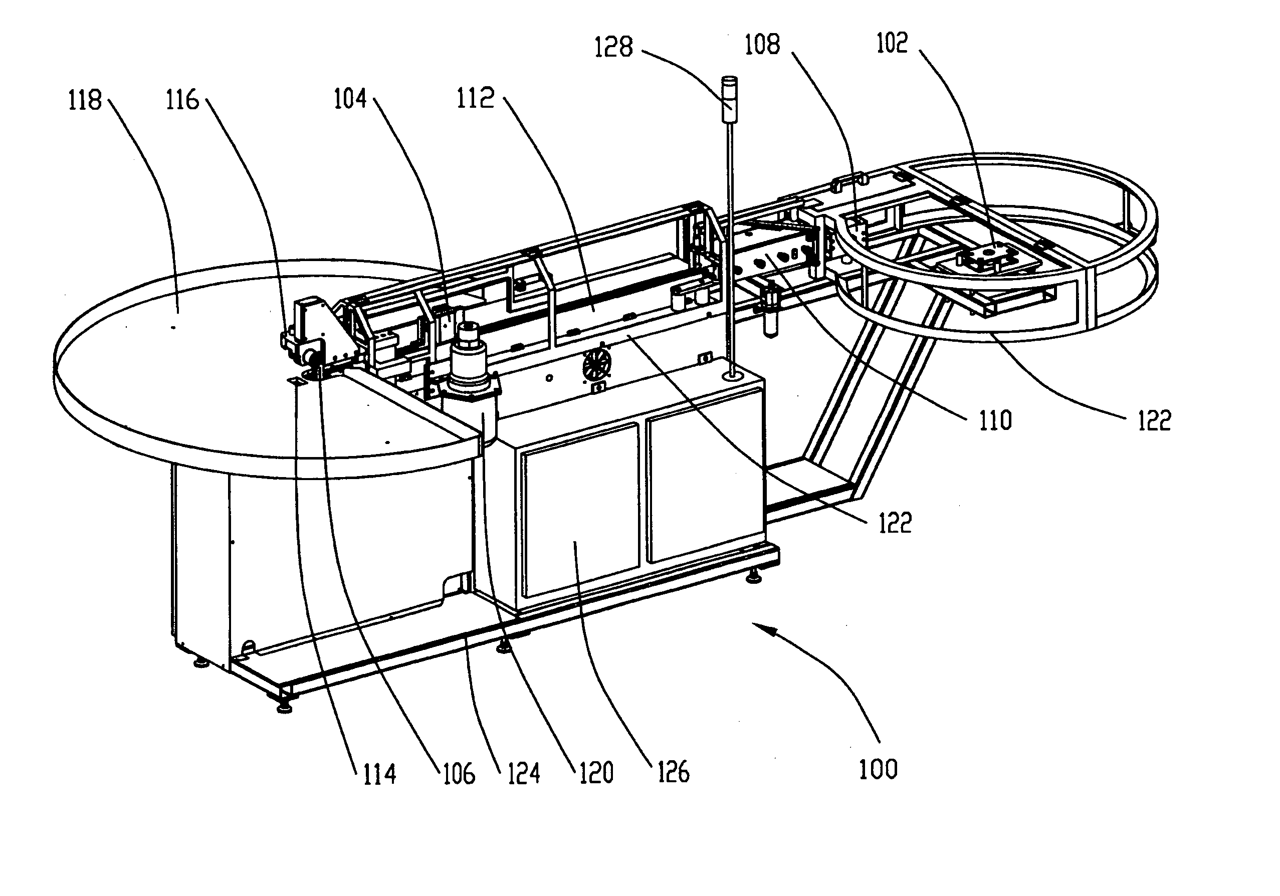
[0044] The production of an accurate cutting die is far from simple. To aid the reader in understanding the complexity of a cutting die, we refer now to FIG. 1a. FIG. 1a is an isometric view of cutting die shown generally as 10. Cutting die 10 is constructed from a piece for material 12 bent at various angles. Material 12 has a cutting edge 14. Cutting edge 14 may be one of many different shapes depending upon the product to be cut by the die 10. Material 12 may have many different characteristics, one having a cutting edge 14 that is heat treated, sharpened and serrated. Die 10 may be reinforced by braces 16 to ensure that die 10 does not deform during use. If used, braces 16 would typically be welded to material 12. Braces 16 may also optionally include one or more mounting holes 18 to allow die 10 to be attached to a cutting board or press (not shown).

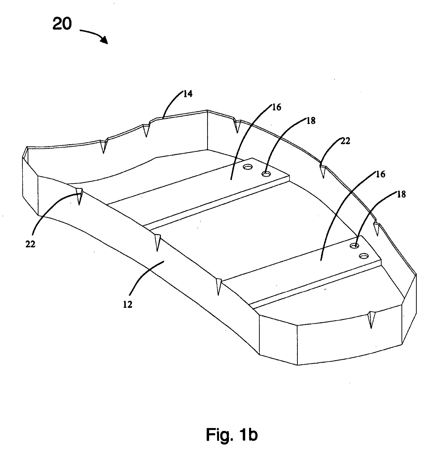
[0045] Referring now to FIG. 1b an isometric view of a cutting die with nicks is shown generally as 20. Cutting die 20 is of the ...


PUM

PropertyMeasurementUnit
thicknessaaaaaaaaaa
heightaaaaaaaaaa
temperaturesaaaaaaaaaa

Abstract

The present invention is a bending machine for bending material such as steel to form cutting dies for products such as cloth, leather or the like. Coiled material is fed through a material washer, straightener and printer by a material feeder to a bending head. If required the material is forwarded through the bending head to a heating unit and retracted to the bending unit to aid in bending. A nicking tool is also provided ahead of the bending tool to nick the material. The nicks enable the cutting die to cut notches in the product being cut. A support surface at the output end of the machine supports the material as it is bent into the required form.

Description

FIELD OF THE INVENTION [0001] The present invention relates generally to a system and method for bending strip material with a sharp cutting edge, such as steel, to create cutting dies. BACKGROUND OF THE INVENTION [0002] When cutting fabric or other materials to meet a specific shape, manufacturers make use of a cutting die. A cutting die is typically a band of steel bent into a desired shape and having a sharpened edge. A cutting die may be then mounted to a base to keep it in place while being used within a press to cut materials. In other uses, such as the cutting of leather the die is not mounted to a base, but attached directly to a cutting device or placed directly on the material to be cut. [0003] Traditionally, a cutting die was bent by hand to conform to the specific shape required. As with classic workmanship, this provided an excellent product. Due to increased labour costs such a method is often no longer economically viable. Thus there has emerged a need to mechanically...

Claims


Application Information

Patent Timeline
Patent Type & Authority Applications(United States)
IPC IPC(8): B21D37/20B23P15/40B26F1/12B26F1/44
CPCB21D7/12B21D37/205B26F2001/4481B26F1/12B26F1/44B23P15/406
Inventor SCOTT, WESLEYDE LA MERCED, MARCUASLOVAK, ALOISBURTCH, MICHAEL
Owner SCOTT WESLEY
Why Eureka
Try Eureka