Eye and ear protection apparatus

a technology for ear protection and eye protection, which is applied in the direction of headwear caps, goggles, hats, etc., can solve the problems of affecting the use of conventional eyeglasses, the tendency of pinching the skull grip of conventional glasses, and the discomfort of wearing separate eye protection devices with separate ear protection devices, so as to reduce or eliminate the discontinuity between lenses and frames, improve the conventional eyeglass configuration, and reduce the effect of impairmen

Inactive Publication Date: 2005-01-27
BRHEL JOSEPH A
View PDF12 Cites 27 Cited by
  • Summary
  • Abstract
  • Description
  • Claims
  • Application Information

AI Technical Summary

Benefits of technology

[0007] The protective apparatus of the present invention has obtained these objects. It provides for a combined eye and ear protective device that has an eye protective portion and an ear protective portion, the eye protective portion and the ear protective portion being functionally cooperating. In the preferred embodiment of the present invention, the protective device utilizes the eye protective portion of the device as the head support for the ear protective portion of the device and configures the eye protective portion in a way that improves on the conventional eyeglass configuration. This combined ear and eye protective device configures the eye protective portion within a single piece of optically clear or visually transparent material that reduces or eliminates the discontinuity between the lenses and frame of conventional eyeglasses. In the preferred embodiment, the unitary construction of the eye protective portion of the device reduces or eliminates impairment of the user's field of view and actually enhances it by providing for unimpeded peripheral vision. A one piece polycarbonate eye protective portion includes a generally rigid front portion that covers the user's eyes and includes a certain amount of flexibility at peripheral portions. The eye protective portion is coupled with the ear protective portion to allow the eye protective portion to move between a “down” position, where the eye protective portion is appurtenant to the user's eyes, and an “up” position, where the eye protective portion is raised up and out of the user's visual field. In this fashion, the ear protective portion of the device remains intact and fully effective against potentially ear damaging noise levels irrespective of whether the eye protective portion is in use or not. In the preferred embodiment, the eye protective portion can also be manufactured in a variety of lenses and in a variety of filters to further enhance the user's visual acuity as desired or required.

Problems solved by technology

In the experience of this inventor, the wearing of a separate eye protective device with a separate ear protective device can be uncomfortable.
For example, the use of earmuff ear protectors very often has the tendency of “pinching” the skull grips of conventional glasses, especially behind the user's ears.
This can be particularly uncomfortable when the user is wearing safety glasses over regular corrective glasses.
This discomfort makes the user more apt to wear one or the other of the protective devices.
Additionally, conventional glasses may need to be removed intermittently for close-up, unimpeded visualization.
Wearing earmuff ear protectors makes this an inconvenient proposition and also one that compromises the safety of the user when the user removes either protective device.
Furthermore, the use of conventional safety glasses with earmuff ear protectors has a tendency to break a portion of the earmuff seal about the user's ears thereby rendering the hearing protection afforded by the ear protectors less effective.
In the experience of this inventor, such devices have practical limitations that are not readily apparent until the devices are placed into practice.
This adds to the complexity of the device as well as increased costs of production.

Method used


Image

  • Eye and ear protection apparatus
  • Eye and ear protection apparatus
  • Eye and ear protection apparatus

Examples


Embodiment Construction

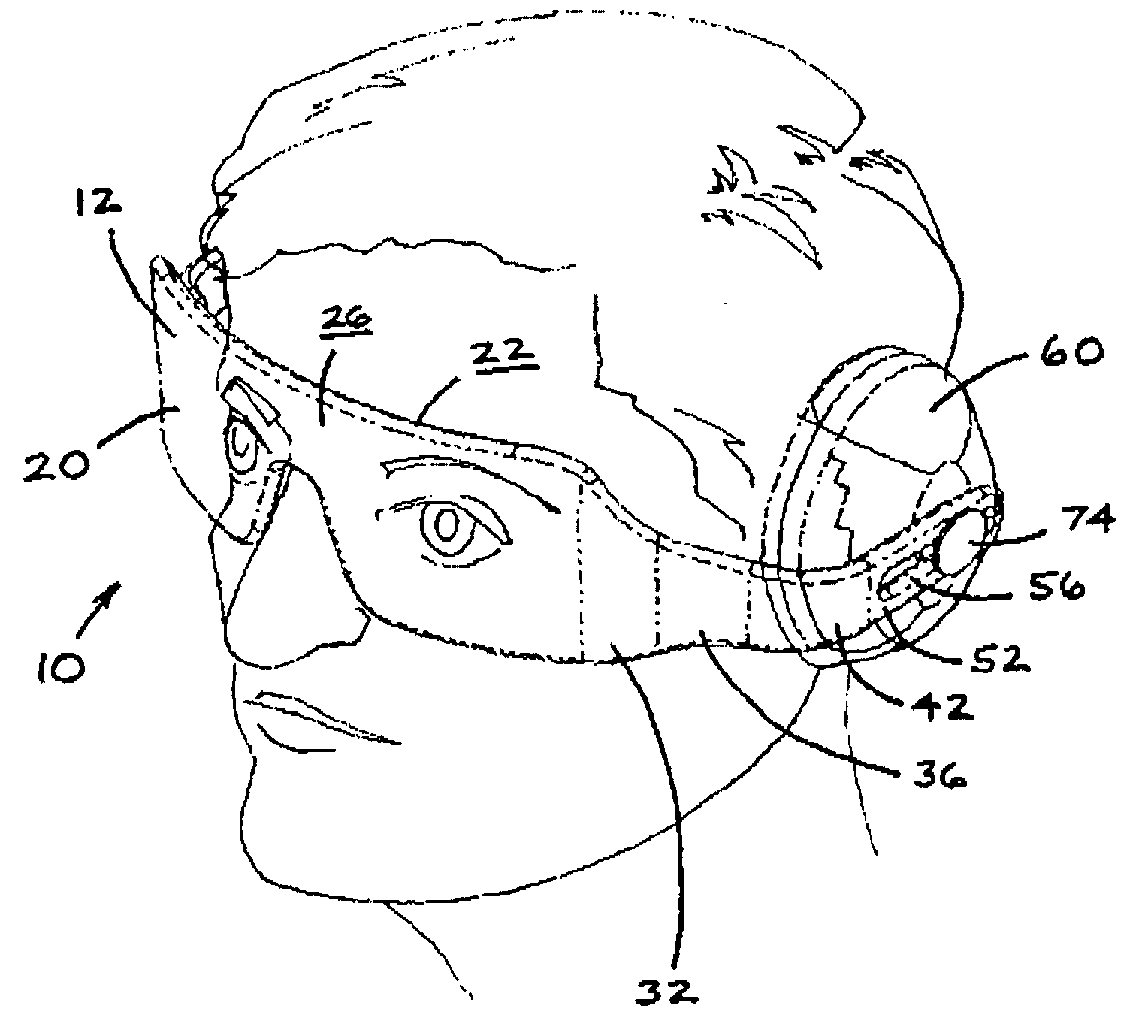
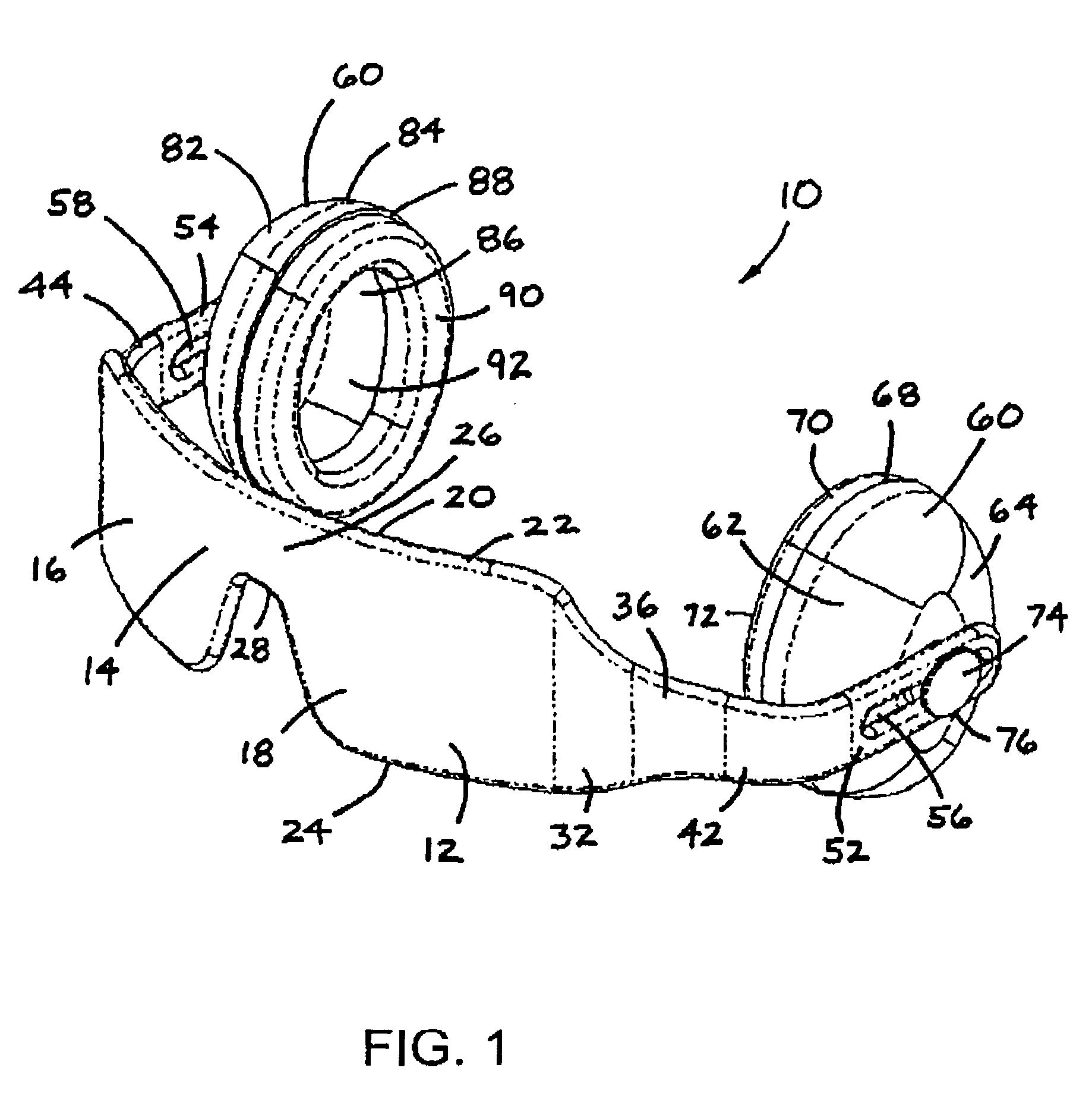
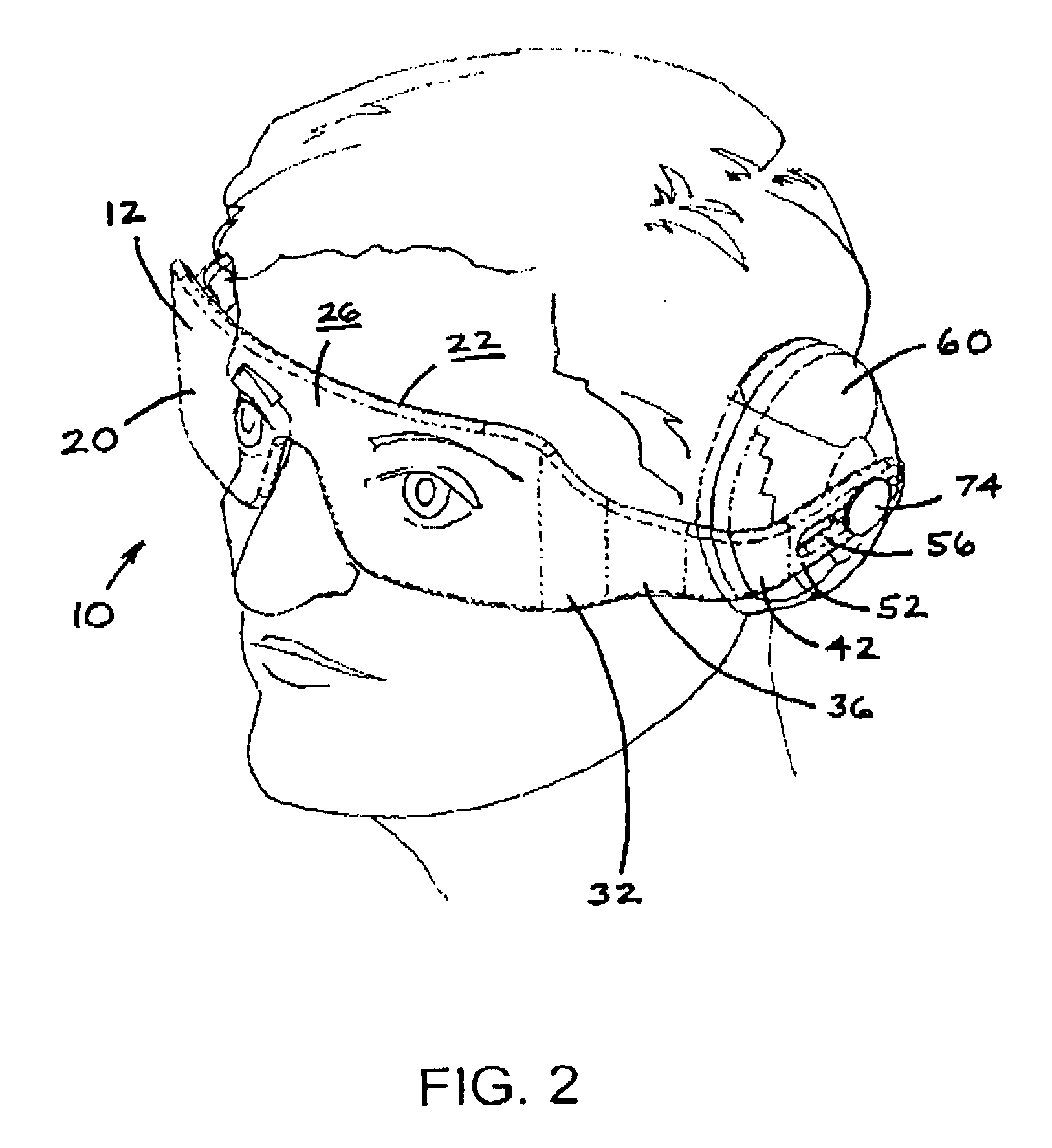
[0013] Referring now to the drawings in detail wherein like numbers represent like elements throughout, FIG. 1 illustrates a perspective view of one embodiment of the eye and ear protective device, generally identified 10, constructed in accordance with the present invention. As shown, the protective device 10 includes the essential elements of an eye protection portion 20 and an ear protection portion 60.

[0014] As shown in FIG. 1, the eye protection portion 20 of the protective device 10 comprises a continuous, substantially planar and symmetrical eye protection member 12. The eye protection member 12 has a frontal portion 14 that is functionally adapted to cover the frontal portion of a user's visual field. See also FIG. 2. This frontal portion 14 includes a pair of optically clear or visually transparent and symmetrical lens portions 16, 18. The lens portions 16, 18 are integrally connected to one another by means of a nose bridge portion 26. The frontal portion is further defin...


PUM


Abstract

A combined eye and ear protective device has an eye protective portion and an ear protective portion, the eye protective portion and the ear protective portion being functionally cooperating. The protective device utilizes the eye protective portion of the device as the head support for the ear protective portion of the device and configures the eye protective portion within a single piece of optically clear material that reduces or eliminates the discontinuity between the lenses and frame of conventional eyeglasses and provides for unimpeded peripheral vision. A one piece polycarbonate resin eye protective portion is coupled with the ear protective portion to allow the eye protective portion to move between a “down” position and an “up” position.

Description

BACKGROUND OF INVENTION [0001] This invention relates generally to protective devices used by human beings. More particularly, it relates to an apparatus that is configured to provide both protection for a user's eyes and ears by use of the same device. [0002] Eye protective devices have been around for many years and are old art. Such devices find use in the workplace by millions of workers every day. Protective eyeglasses are indeed mandated by federal and state safety standards in factory settings and manufacturing facilities. Eyeglass frames having separate protective lenses are most often used. Other specialized eye protective devices have been devised for welders, painters, and other industrial professionals and often take the form of an eye and face shield. When such devices are not in use, they may simply be removed and stowed away for later use. Other configurations allow for the eye protective device to be rotatably moveable away from and out of the user's visual field. It...

Claims


Application Information

Patent Timeline
Patent Type & Authority Applications(United States)
IPC IPC(8): A42B1/06A61F9/02A61F11/14
CPCA61F11/14A61F9/029
Inventor BRHEL, JOSEPH A.
Owner BRHEL JOSEPH A
Why Eureka
Try Eureka