Stripping apparatus and process

a technology of stripping apparatus and process, applied in the direction of lighting and heating apparatus, separation process, furnace, etc., can solve the problems of product waste, loss of conversion and valuable product yield, and possible reaction of dealkylation and condensation, so as to prevent stagnation zones

Active Publication Date: 2005-02-24
PETROLEO BRASILEIRO SA (PETROBRAS)
View PDF16 Cites 40 Cited by
  • Summary
  • Abstract
  • Description
  • Claims
  • Application Information

AI Technical Summary

Benefits of technology

The present invention provides further a process for stripping hydrocarbons adsorbed on solid particles comprising passing said particles counter-currently with a gaseous stripping fluid in a vertical stripping chamber past said set of series of at least

Problems solved by technology

Depending on the operational conditions, some cracking, dealkylation and condensation reactions may also occur.
Strippable hydrocarbons not desorbed in the stripping step are directed to the regenerator, causing product waste.
High regeneration temperatures result in deep catalytic deactivation and limit catalyst circulation, leading to losses in conversion and valuable product yields.
According to the practiced temperature levels, even the stripper itself may be jeopardized in view of the metallurgical limit.
Poor stripping reduces the amount of recoverable product.
Perhaps, more importantly, poor strippping can cause excessively high regenerator temperatures, which reduce catalyst circulation, unit severity and conversion.
Higher regenerator temperatures also lead to faster catalyst deactivation and increased mechanical wear on the unit.
High temperatures increase vanadium mobility and promote the formation of acidic species, which attack the catalyst structure, leading to permanent activity loss.
As regards the stripper role, it should be mentioned that any modification introduced in the unit aiming at reducing delta coke, such as for example, n

Method used


Image

  • Stripping apparatus and process
  • Stripping apparatus and process
  • Stripping apparatus and process

Examples


Embodiment Construction

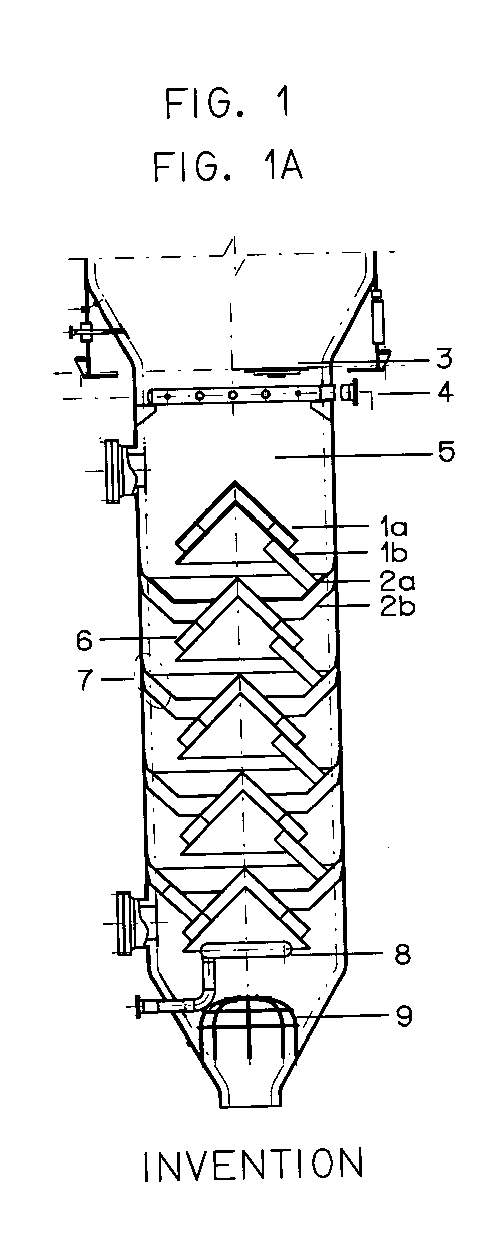
One aspect of the present invention is an apparatus for stripping hydrocarbons adsorbed on fluidized solid particles, such as spent catalysts used in a FCC unit.

A further aspect of the invention is a stripping process for stripping such adsorbed hydrocarbons from fluidized solid particles such as those of a spent catalyst used in a FCC unit.

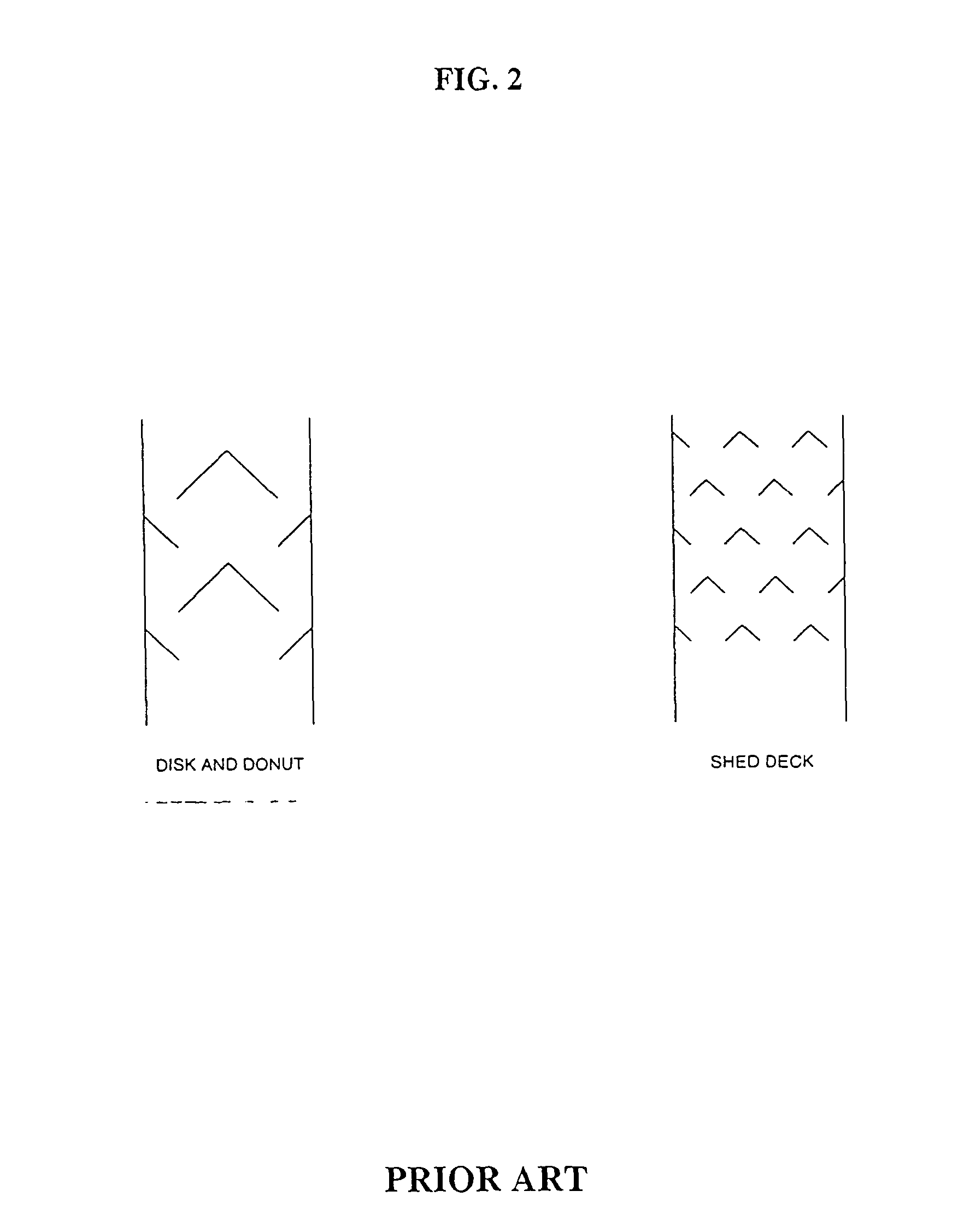
At the end of the riser, it is important to make a quick separation between the catalyst and the product vapors. This will minimize cracking reactions in the reactor vessel. The current state-of-the-art in riser terminations is closed cyclones. These systems minimize reactor dilute phase residence time by connecting the riser cyclone outlets directly to the inlets of the reactor cyclones. Catalyst from the cyclones flows directly into the reactor bed. This catalyst flow does, however, carry some product vapors into the bed. These vapors are recovered in the stripper.

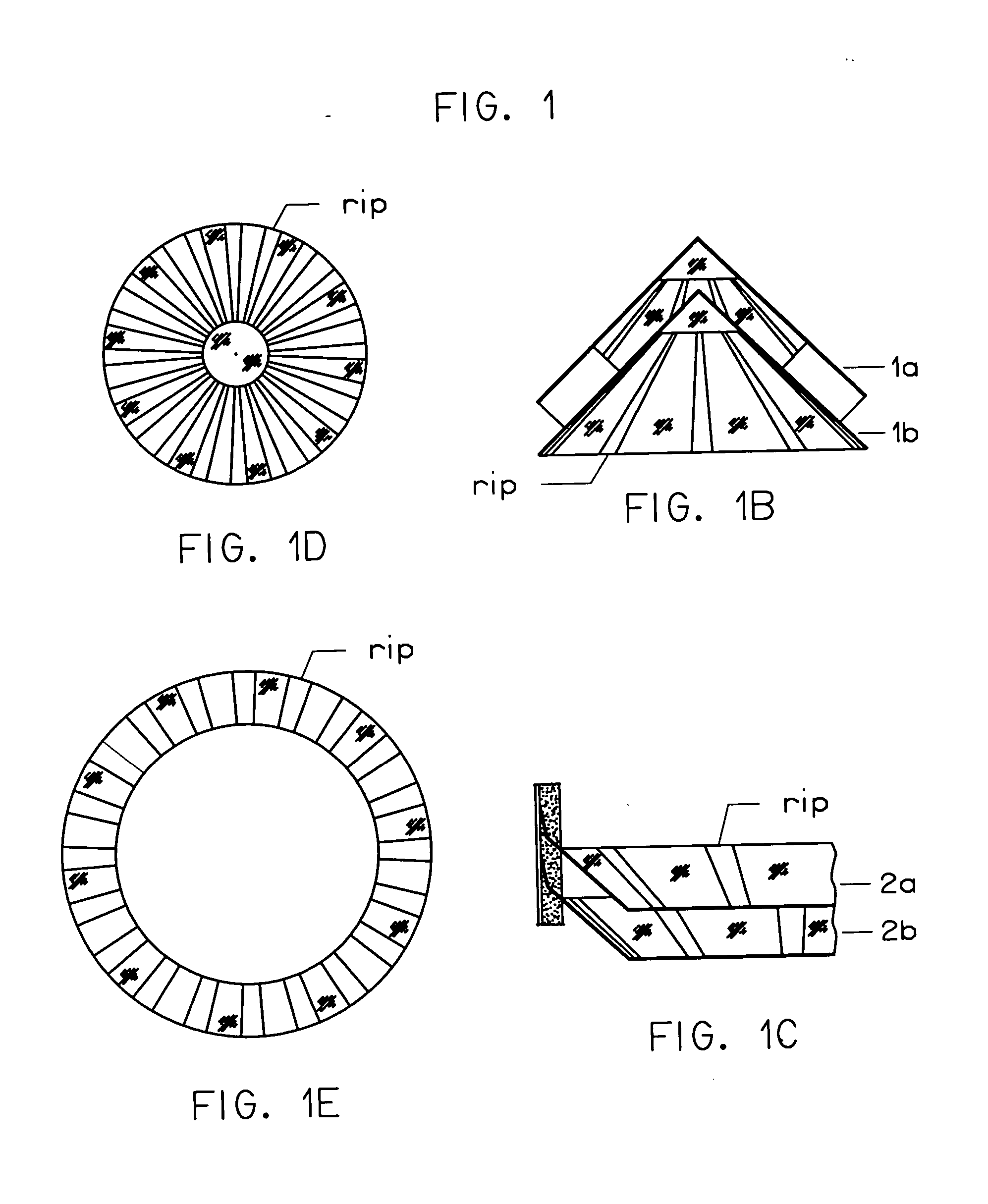
As generally represented in FIG. 1A, a stripper apparatus according to the...


PUM

PropertyMeasurementUnit
Fractionaaaaaaaaaa
Fractionaaaaaaaaaa
Fractionaaaaaaaaaa

Abstract

A stripping apparatus for desorbing gases from solid particles through which flows counter-currently a stripping fluid is described, which comprises a series of sets of at least two parallel, segmented, baffle plates each, with the segmented baffles being oriented so that the rows are offset relative to rows of other levels, where the thickness and separation of said sets of baffles is so dimensioned as to reduce coalescence of the size of the formed bubbles and optimize the hydrocarbons desorption from said fluidized solid particles. The solid particles are mainly spent catalyst particles from a FCC process. The stripping process to be carried out in a fluidized bed comprises contacting the spent catalyst with a stripping fluid that flows upwardly in the fluidized bed in the form of bubbles. Adsorbed hydrocarbons present in the spent catalyst are transferred from the catalyst emulsion that flows downwardly to the upwardly moving bubbles, so as to promote the efficient recovery of cracked products.

Description

FIELD OF THE INVENTION The present invention relates to a stripping apparatus and process, more specifically, to a stripping apparatus useful for gas-solid separation processes, such as fluid catalytic cracking unit (FCC), the apparatus being provided with at least two sets of parallel, segmented baffle plates placed in series, the design and arrangement of which secures improved contact between gas and spent catalyst solid. As a result, catalyst recirculation zones associated to dead zones are reduced and consequently the time required for removal of extractable hydrocarbons is reduced. According to the stripping process of the invention, the spent FCC catalyst is made to counter-currently contact the bubbles of a stripping fluid that flows upward the fluidized bed. Adsorbed hydrocarbons on the spent catalyst are transferred from the catalyst emulsion that flows downwardly to the upwardly flowing bubbles, so as to promote the recovery of cracking products. BACKGROUND INFORMATION ...

Claims


Application Information

Patent Timeline
IPC IPC(8): B01D45/08B01J8/00B01J8/18C10G11/00C10G11/05C10G11/18
CPCB01D45/08C10G11/182C10G11/05B01J8/18
Inventor CERQUEIRA, HENRIQUE SOARESALVARENGA BAPTISTA, CLAUDIA M DE LACERDAFUSCO, JOSE MOZART
Owner PETROLEO BRASILEIRO SA (PETROBRAS)
Why Eureka
Try Eureka