Inclined micro-spraying cold plate

A tilting, cold plate technology, applied in the direction of electrical components, electrical solid devices, circuits, etc., can solve the problems of spray heat exchange effect not reaching the best, heat exchange surface coverage rate is not high, and achieve efficient heat dissipation and high coverage rate Effect

Pending Publication Date: 2021-09-24
CHANGZHOU UNIV
View PDF0 Cites 0 Cited by
  • Summary
  • Abstract
  • Description
  • Claims
  • Application Information

AI Technical Summary

Problems solved by technology

If the nozzles are arranged in an inclined manner, although the stagnation zone is weakened, the coverage of the heat transfer surface is not high, and the spray heat transfer effect is not optimal.

Method used


Image

  • Inclined micro-spraying cold plate
  • Inclined micro-spraying cold plate
  • Inclined micro-spraying cold plate

Examples


Embodiment 1

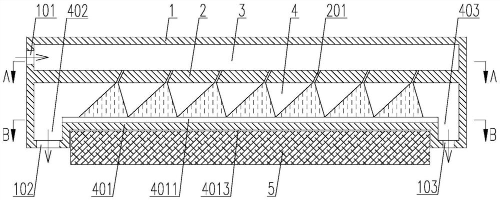
[0034] Such as Figure 1-3 As shown, a kind of inclined type micro-spray cold plate includes a cold plate body 1, which has an inner cavity in the cold plate body 1, and a partition 3 is fixed in the inner cavity, and the partition 3 separates the inner cavity into The upper static pressure chamber 3 and the lower spray chamber 4;

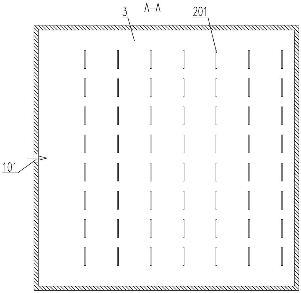
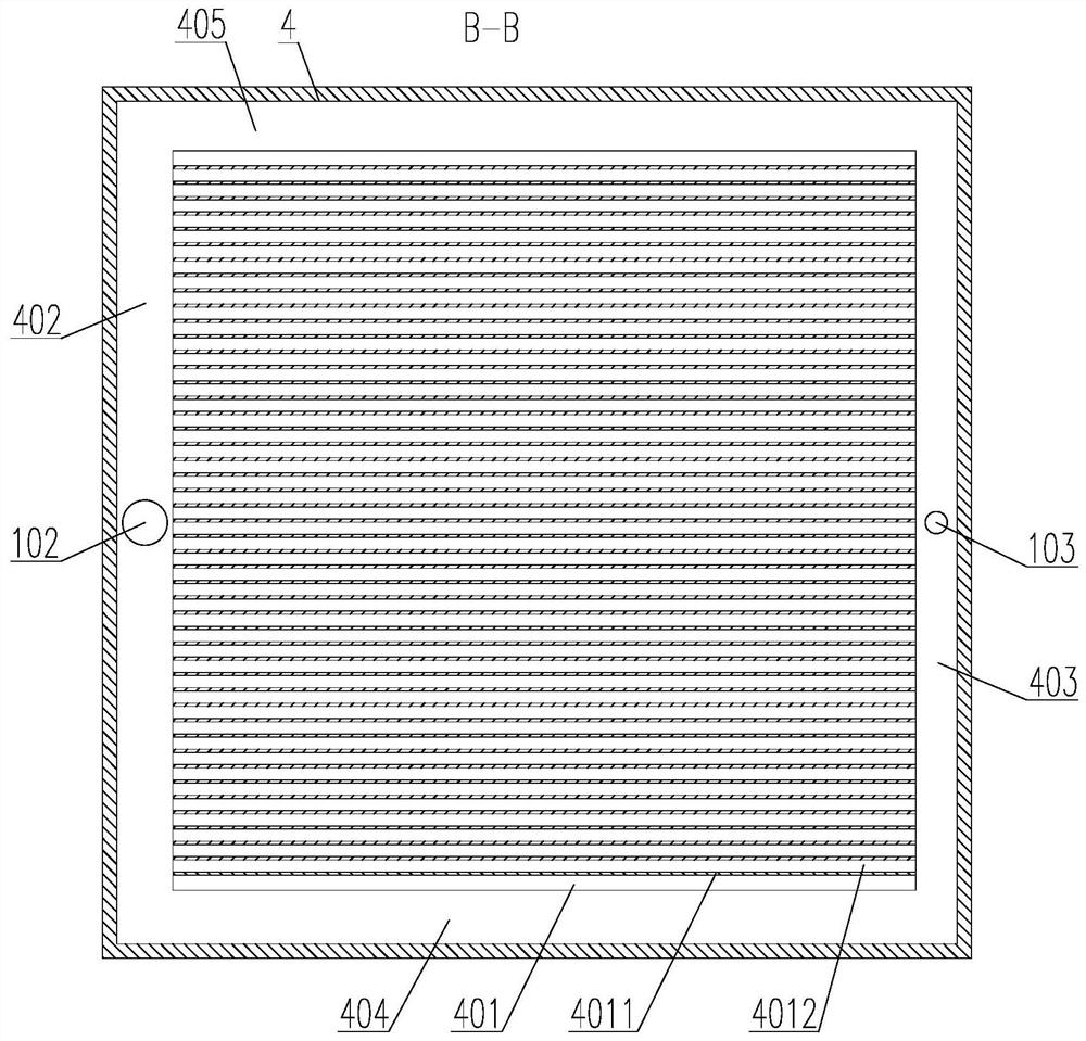
[0035] A heat exchange platform 401 protrudes upwards from the middle part of the bottom of the spray chamber 4, and the partition plate 3 has a spray hole group, and the spray hole group includes a number of flat spray holes 201 penetrating through the partition plate 3. The cross-section of the beam of the nozzle hole 201 is square, and several flat nozzle holes 201 are distributed on the partition plate 3 in an array. On the upper surface of the heat platform 401, a liquid discharge channel is formed between the outer surface of the heat exchange platform 401 and the inner peripheral surface of the spray chamber 4, and the outer wall of the col...


PUM

PropertyMeasurementUnit
Widthaaaaaaaaaa
Lengthaaaaaaaaaa

Abstract

The invention relates to the technical field of heat dissipation devices, in particular to an inclined micro-spraying cold plate which comprises a cold plate body, an inner cavity is formed in the cold plate body, and a partition plate divides the inner cavity into a static pressure cavity located on the upper portion and a spraying cavity located on the lower portion. The middle part of the bottom of the spraying cavity protrudes upwards to form a heat exchange platform, the spraying hole set comprises a plurality of flat spraying holes penetrating through the partition plate, and the cross section of a cross beam of each flat spraying hole is in a square shape. And meanwhile, the cross sections of the flat spraying holes are square, spraying cones sprayed by the flat spraying holes are roughly of a rectangular pyramid structure, and therefore the upper surface of the heat exchange platform is basically covered under the condition that every two adjacent spraying cones do not intersect and interfere with each other, and the coverage rate is high, so that the heat source below the heat exchange platform can be uniformly and efficiently cooled.

Description

technical field [0001] The invention relates to the technical field of heat dissipation devices, in particular to an inclined micro-spray cold plate. Background technique [0002] Spray cooling heat transfer technology is a research hotspot in recent years, but some problems have also been found in the research process. For example, the central position of the spray heat exchange surface is prone to produce a stagnation zone, and the flow of working fluid in the stagnation zone is restricted, resulting in a local temperature rise. However, the method of placing the nozzle at an angle can effectively prevent the stagnation zone and effectively prevent the stagnation zone. Conducive to the flow organization of working fluid. In addition, most of the existing nozzle spray cones are circular, and for common heat sources such as chips, the combination of multiple circular spray cone nozzles will inevitably produce a large range of dead angles that cannot be covered around, which...

Claims


Application Information

Patent Timeline
IPC IPC(8): H01L23/473H01L23/367
CPCH01L23/473H01L23/4735H01L23/3672
Inventor 周年勇冯浩范婕刘文博郭艺星彭浩平邓嵩雷云
Owner CHANGZHOU UNIV
Why Eureka
Try Eureka