
Improved fuel cell stack flow hood air flow using air distribution device

A fuel cell stack, fuel cell technology, applied in fuel cells, fuel cell grouping, fuel cell additives, etc., can solve problems such as increased complexity and unsatisfactory, achieve size and mass reduction, prolong service life, temperature The effect of gradient reduction

Active Publication Date: 2013-10-30
CERES INTPROP CO LTD
View PDF32 Cites 0 Cited by
  • Summary
  • Abstract
  • Description
  • Claims
  • Application Information

AI Technical Summary

Problems solved by technology

This is undesirable because it adds complexity to the manufacture of the fuel cell stack and fuel cell stack components, and leads to additional complexity in the control of fuel cell stack operations

Method used


Image

  • Improved fuel cell stack flow hood air flow using air distribution device
  • Improved fuel cell stack flow hood air flow using air distribution device
  • Improved fuel cell stack flow hood air flow using air distribution device

Examples


Embodiment Construction

[0189] The teachings of fuel cells and fuel cell stack assemblies are well known to those of ordinary skill in the art and include in particular US 6794075, WO 02 / 35628, WO 03 / 075382, WO 2004 / 089848, WO 2005 / 078843, WO 2006 / 079800 , WO 2006 / 106334, WO 2007 / 085863, WO 2007 / 110587, WO 2008 / 001119, WO 2008 / 003976, WO 2008 / 015461 and WO 2008 / 053213, all of which are hereby incorporated by reference in their entirety.

[0190] A summary of the reference signs used herein is given before the claims.

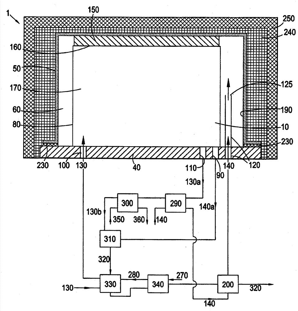
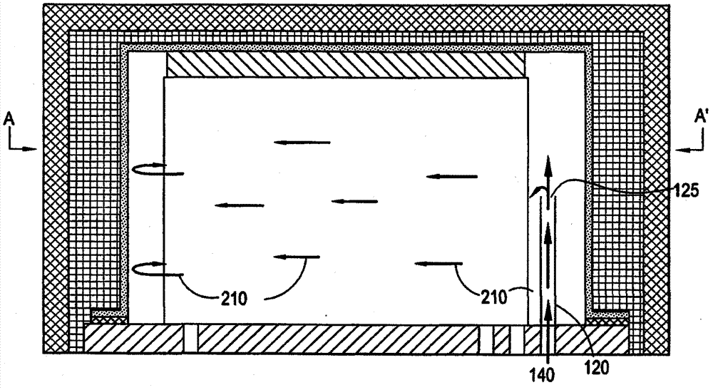
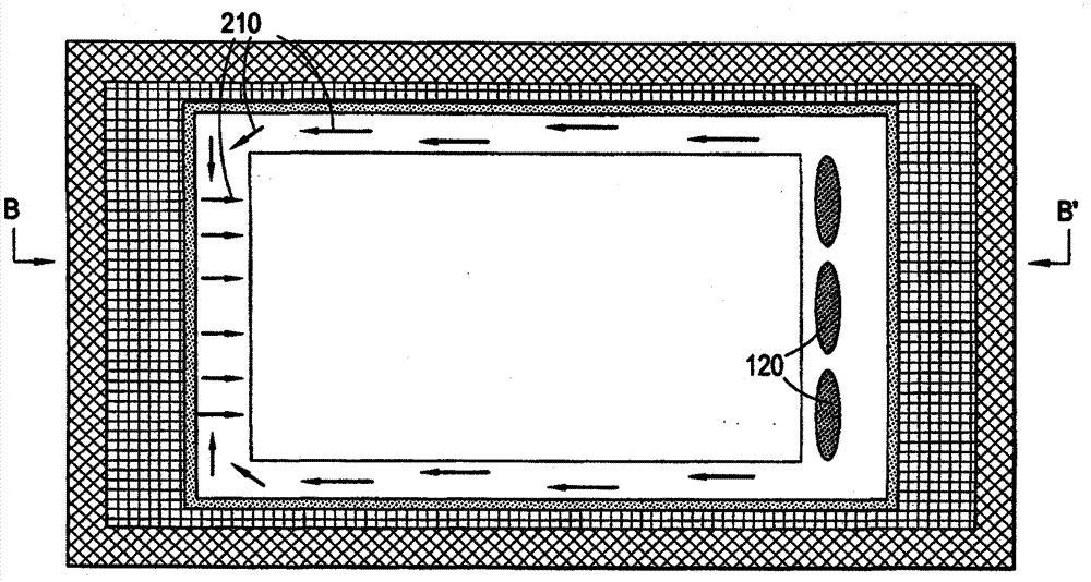
[0191] In the first embodiment of the fuel cell stack assembly 1, the solid oxide fuel cell stack 10 is assembled from a plurality of fuel cell stack layers 20, and each fuel cell stack layer 20 includes a fuel cell 30 (in other embodiments For example, not shown, each fuel cell stack 20 includes a plurality of fuel cells 30). Each fuel cell includes an anode 31, an electrolyte 32, and a cathode 33, wherein the anode 31, the electrolyte 32, and the cathode 33 are mounted on a fuel cel...


PUM


Abstract

The present invention is concerned with improved fuel cell stack assemblies, and methods of operation of a fuel cell stack assembly, particularly with improved gas flow and thermal management.

Description

technical field [0001] The present invention relates to improved fuel cell stack assemblies and methods of operating fuel cell stack assemblies, particularly to improved airflow and thermal management. Background technique [0002] The term "fuel cell stack assembly" as used herein means at least one fuel cell stack each comprising at least one fuel cell stack layer and a fuel cell for one or more fuel and oxidant streams used a stack floor and a cover sealingly connected to the fuel cell stack floor, at least one gas inlet into the cover volume, and a preheater (not located in the cover volume), wherein at least one fuel cell stack layer each includes at least one A fuel cell, fuel and oxidant inlet / outlet connections, and flow paths for one or more fuel and oxidant streams define a shroud volume between the fuel cell stack base plate and the shroud. Other optional components of the fuel cell stack assembly suitably include fuel side seal assemblies, oxidant side seal asse...

Claims


Application Information

Patent Timeline
Patent Type & Authority Patents(China)
IPC IPC(8): H01M8/24H01M8/04
CPCH01M8/2475H01M8/04014H01M8/04089Y02E60/50H01M8/2485H01M8/2425H01M8/2483H01M8/2484H01M8/04H01M8/12H01M8/24H01M8/2465
Inventor 保罗·巴纳尔内维尔·海德尔马修·哈林顿
Owner CERES INTPROP CO LTD
Learn More