Inkjet recording device and inkjet recording method

a recording device and inkjet technology, applied in typewriters, printing, other printing apparatus, etc., can solve the problems of poor yield, limit to high production, and limit to high production, and achieve the effect of high production and head restoration

Inactive Publication Date: 2005-03-03
FUJIFILM BUSINESS INNOVATION CORP
View PDF2 Cites 105 Cited by
  • Summary
  • Abstract
  • Description
  • Claims
  • Application Information

AI Technical Summary

Benefits of technology

[0019] Because the present invention has the above-described structure, the produceability is high, head restoring o

Problems solved by technology

However, on the other hand, because reciprocal movement of the inkjet recording head (main scanning) at the time of image recording is essential, limits to the pursuit of high produceability (carrying out image recording on more recording media per unit time) arise as a matter of course.
Thus, there are cases in which the yield is poor.
In structures such as these in which the head restoring unit is moved, it is not possible to carry out restoring operations (dummy jetting and the like) in continuation while image re

Method used


Image

  • Inkjet recording device and inkjet recording method
  • Inkjet recording device and inkjet recording method
  • Inkjet recording device and inkjet recording method

Examples


first embodiment

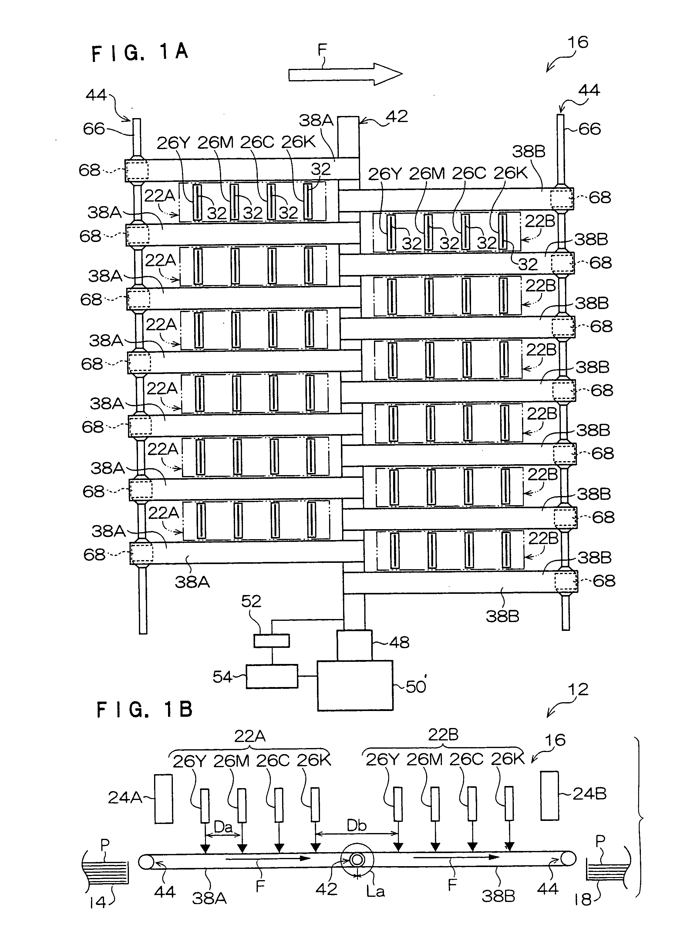
[0043] The schematic structure of an inkjet recording device 12 of the present invention is shown in FIGS. 1 through 3.

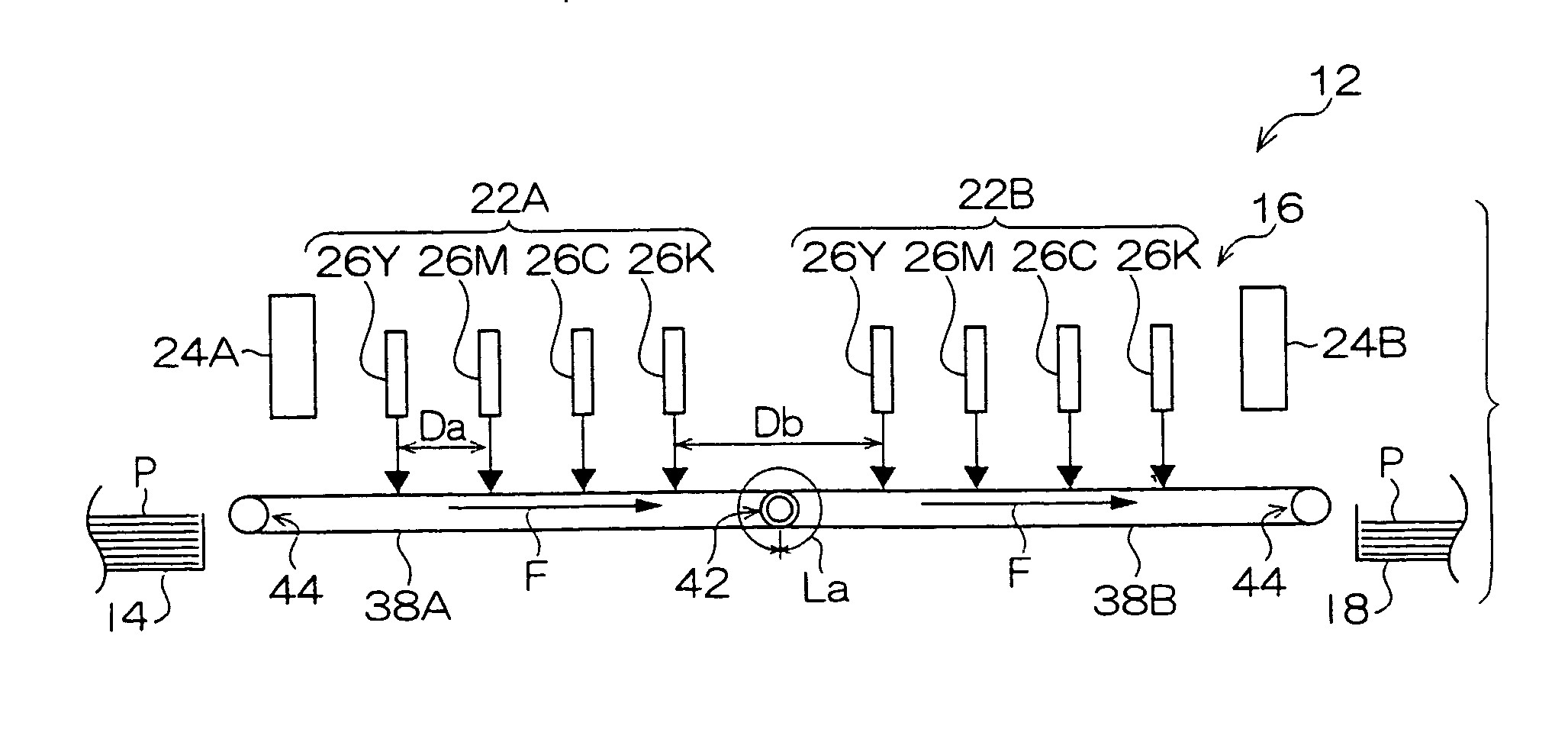
[0044] As shown in FIG. 1B, the inkjet recording device 12 has a sheet feeding tray 14 in which sheets P, which are one example of a recording medium, are accommodated; a recording section 16 recording images onto the sheets P supplied from the sheet feeding tray 14; and a sheet discharge tray 18 accommodating the sheets P on which images have been formed by the recording section 16. The sheets P in the sheet feeding tray 14 are removed one-by-one by a pick-up roller (not shown), and fed to the recording section 16.

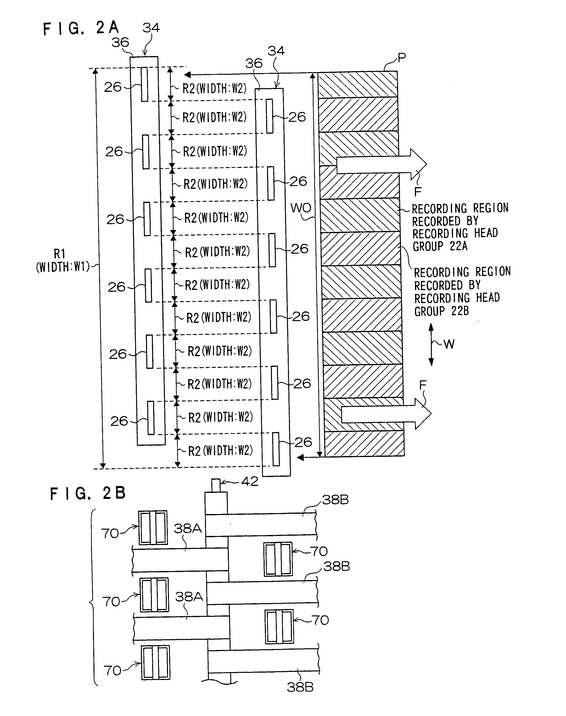
[0045] As shown in FIG. 3, the recording section 16 has a frame-shaped sheet conveying frame 20 which is mounted to a housing (not shown). The sheet P is conveyed in a predetermined conveying direction on the sheet conveying frame 20. In the respective drawings, the sheet conveying direction is denoted by arrow F, and the sheet transverse direction, whic...

second embodiment

[0097] Note that, in the second embodiment as well, a distance Db′ between nozzles of the unit heads 26 between the recording head groups 22A, 22B is preferably substantially a natural number multiple of the circumference La′ of the drive roller 76.

third embodiment

[0098] A third embodiment illustrated in FIG. 11 is structured to include, in addition to the recording head groups 22A, 22B, recording head groups 22C, 22D which are further downstream, such that there are four of the recording head groups 22. In correspondence therewith, there are four slave rollers 44, and four sheet conveying belts 38A, 38B, 38C, 38D are disposed in that order from the upstream side. Accordingly, as shown as an example in FIG. 12A, the arrangement of the recording head groups as seen in plan view repeats in the order of the recording head group 22A, the recording head group 22C, the recording head group 22B, and the recording head group 22D from the top side of the drawing.

[0099] In this way, when there is a large number of recording head groups, as can be understood from FIGS. 12A and 12B, the interval between adjacent unit heads 26 in the sheet transverse direction within a single recording head unit 34 can be made to be greater than that in the first embodime...


PUM


Abstract

Provided is an inkjet recording device that has a conveying unit for conveying a recording medium, plural recording head groups each structured by plural unit heads disposed along the conveying direction, and an ink receiving unit for receiving ink discharged from the unit heads. The recording head groups, correspond respectively to plural individual recording regions which are sectioned off in the recording medium transverse direction which is orthogonal to the conveying direction, are disposed so as to be at respectively different positions at adjacent individual recording regions along the conveying direction. The ink receiving unit is disposed so as to face ink drop discharging surfaces of the unit heads. The conveying unit is plural conveying belts disposed at positions evading trajectories of the ink drops from the unit heads as seen in a direction of a line normal to the recording medium so as to be divided in the conveying direction.

Description

CROSS-REFERENCE TO RELATED APPLICATION [0001] This application claims priority under 35 USC 119 from Japanese Patent Application No.2003-302800, the disclosure of which is incorporated by reference herein.BACKGROUND OF THE INVENTION [0002] 1. Field of the Invention [0003] The present invention relates to an inkjet recording device and an inkjet recording method, and in particular, to an inkjet recording device which carries out recording by discharging ink drops onto a recording medium, and to an inkjet recording method which records an image on a recording medium by the inkjet recording device. [0004] 2. Description of the Related Art [0005] Among inkjet recording devices which record an image by discharging ink drops onto a recording medium such as a sheet or the like, there are so-called scanning inkjet recording devices in which an inkjet recording head is installed at a moving member such as a carriage or the like, and movement of the inkjet recording head in the direction orth...

Claims


Application Information

Patent Timeline
IPC IPC(8): B41J2/01B41J2/175B41J3/54B41J11/00
CPCB41J11/007B41J3/543
Inventor ANDO, RYOSATOH, HIROAKINISHIKAWA, SATORUTAGAWA, KOZOKATO, TAKESHIUDAKA, TSUTOMUKAZAMA, TOSHIYUKIMATSUZAKI, YOSHIKIGOTO, OSAMUKIBAYASHI, SUSUMUMITAMURA, YOSHIHIKO
Owner FUJIFILM BUSINESS INNOVATION CORP
Why Eureka
Try Eureka