One-branch stent-graft for bifurcated lumens

a one-branch stent and bifurcated technology, applied in the field of stent grafts, can solve the problems of significant disadvantages in and the distal migration associated with the use of prior art prostheses

Inactive Publication Date: 2005-03-03
LIFESHIELD SCI
View PDF12 Cites 42 Cited by
  • Summary
  • Abstract
  • Description
  • Claims
  • Application Information

AI Technical Summary

Benefits of technology

[0006] A stent-graft of this invention includes a bifurcated stent, i.e., an unbifurcated portion in fluid communication with two branches. The stent-graft further includes a graft that lines or covers at least part of the bifurcated stent. The graft of this stent graft defines a fluid passageway from the unbifurcated portion into one of the bifurcated stent branches. A closure, which may be part of the graft, prevents fluid from flowing to the other of the branches. The stent-graft is preferably adapted for placement of the stent bifurcation adjacent the native bifurcation of a body lumen to resist distal migration of the stent-graft. One use of such stent-grafts is in bypassing abdominal aortic aneurysms where a femoral-femoral bypass is surgically installed to provide blood flow to the occluded iliac.
[0008] According to yet another aspect of this invention, a stent-graft adapted for placement at a native vessel bifurcation includes a bifurcated stent with a proximal portion adapted for placement in an unbifurcated region of the native bifurcation. The bifurcated stent further includes two distal portions. The first distal portion is adapted to extend from the unbifurcated region of the native bifurcation into one of the bifurcated branches of the native bifurcation. The second distal portion extends toward and into the other bifurcated branch of the native bifurcation. A graft lining or covering defines a fluid passage that extends from the proximal portion of the bifurcated stent to the distal portions of the bifurcated stent. An occluder device is adapted for placement in the second distal portion. The occluder prevents fluid passage through the second distal portion of the bifurcated stent-graft and to the second branch of the bifurcated lumen.

Problems solved by technology

In particular, where the site of desired application of the stent or prosthesis is a native vessel bifurcation, the distal migration associated with the use of the prior art prostheses constitutes a significant disadvantage.

Method used


Image

  • One-branch stent-graft for bifurcated lumens
  • One-branch stent-graft for bifurcated lumens
  • One-branch stent-graft for bifurcated lumens

Examples


Embodiment Construction

[0021] Although the invention is illustrated and described herein with reference to specific embodiments, the invention is not intended to be limited to the details shown. Rather, various modifications may be made in the details within the scope and range of equivalents of the claims and without departing from the true spirit and scope of the present invention.

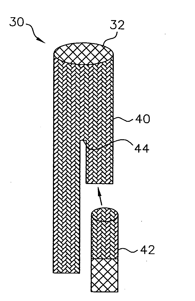
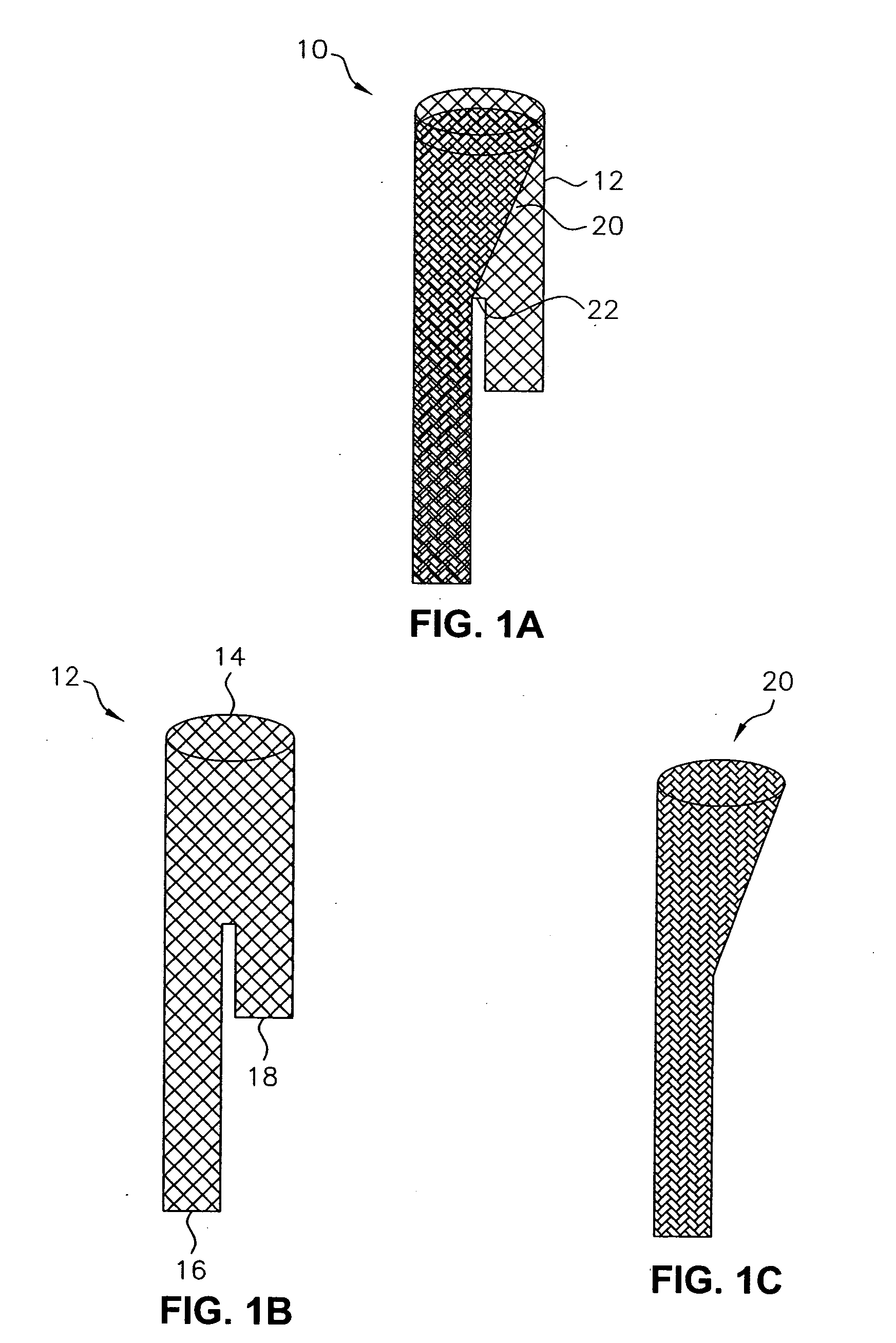
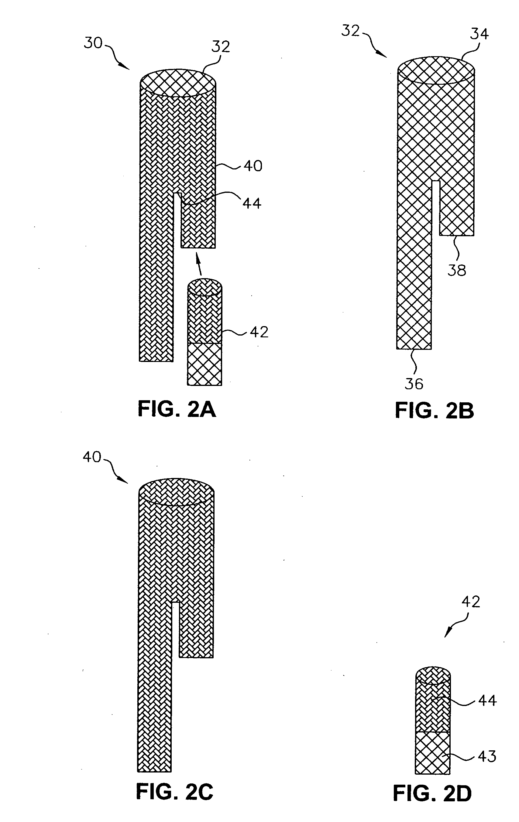
[0022] Referring specifically to FIGS. 1A-1C, there is shown a stent-graft 10 is adapted for placement at a native vessel bifurcation. The stent-graft 10 includes a bifurcated stent 12 with a proximal portion 14 adapted for placement in an unbifurcated region of the native bifurcation. The bifurcated stent 12 further includes two distal portions 16, 18. The first distal portion 16 is adapted to extend from the unbifurcated region of the native bifurcation into one of the bifurcated branches of the native bifurcation. The second distal portion 18 extends toward the other bifurcated branch of the native bifurcation. A graft lin...


PUM


Abstract

A stent-graft is provided that includes a bifurcated stent adapted for placement at the bifurcation of a bifurcated body lumen. The stent-graft further includes a graft that lines or covers at least part of the bifurcated stent. The graft defines a fluid passageway from the unbifurcated portion into one of the bifurcated stent branches. A closure prevents fluid from flowing through the second of the branches and into the other branch of the body lumen.

Description

[0001] This application is a divisional of application Ser. No. 10 / 461,898 filed on Jun. 13, 2003 entitled ONE-BRANCH STENT-GRAFT FOR BIFURCATED LUMENS.FIELD OF THE INVENTION [0002] The present invention relates to a one-branch stent-graft for use in bifurcated body lumens. More specifically, the present invention relates to a stent graft including two branches, wherein a closure prevents fluid from flowing to one of the branches. BACKGROUND OF THE INVENTION [0003] A stent-graft (a stent with a graft layer lining or covering it) is typically used to provide a prosthetic intraluminal wall, e.g., in the case of a stenosis or aneurysm, to provide an unobstructed conduit for blood in the area of the stenosis or aneurysm. A stent-graft may be endoluminally deployed in a body lumen, a blood vessel for example, at the site of a stenosis or aneurysm by so-called “minimally invasive techniques” in which the stent-graft is compressed radially inwards and is delivered by a catheter to the site...

Claims


Application Information

Patent Timeline
Patent Type & Authority Applications(United States)
IPC IPC(8): A61F2/06
CPCA61F2/07A61F2/90A61F2002/075A61F2002/067
Inventor NAZZARO, PATRICEKUJAWSKI, DENNIS
Owner LIFESHIELD SCI
Why Eureka
Try Eureka