
Rack architecture and management system

a management system and rack technology, applied in the field of rack enclosure cabinets, can solve the problems of no products that address the management of the entire rack cabinet and/or the data center of the rack cabinet, and the difficulty of removing, replacing, and/or servicing computers or other devices in the cabinet rack, etc., to achieve the effect of eliminating vertical runs

Active Publication Date: 2005-03-03
CHATSWORTH PROD INC
View PDF26 Cites 75 Cited by
  • Summary
  • Abstract
  • Description
  • Claims
  • Application Information

AI Technical Summary

Benefits of technology

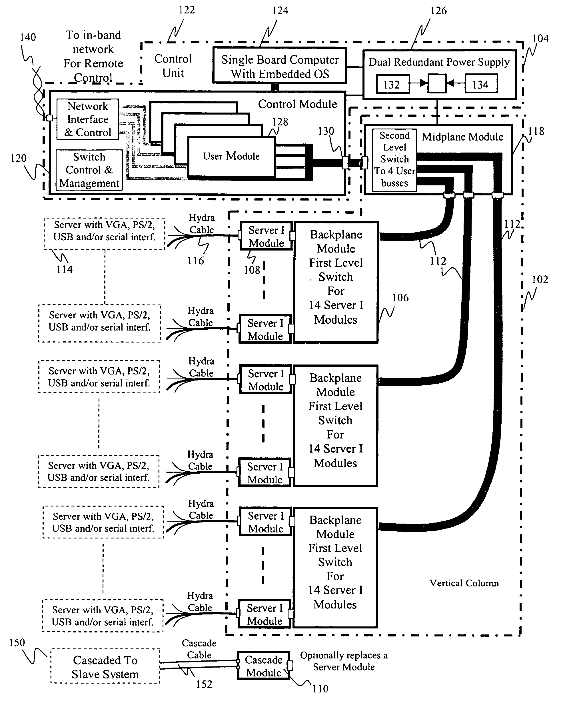
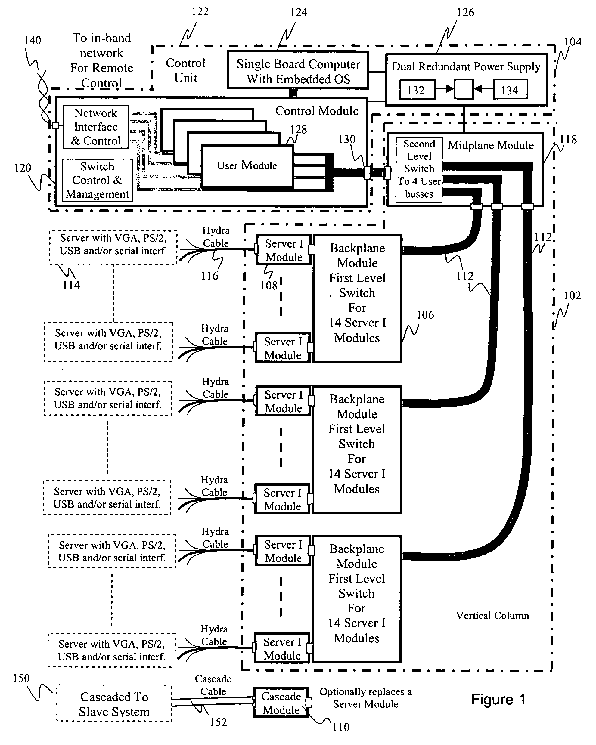
The invention provides a fully distributed, scaleable, and modular rack architecture and management system. It allows for device management throughout the rack with a vertical interface column integrated into the rack cabinet. The vertical column can be populated with 1 to 42 SIM modules, which feed into a control module that facilitates hot-swappable user card slots and allows each rack device to be controlled by one or more concurrent users. The control module also has additional serial management ports and a dedicated port for an optional external modem in case of a catastrophic network failure. The invention provides centralized management of server, network, power, and environmental equipment within a rack cabinet to a single IP address and allows customers to grow their infrastructure without the need to invest in oversized equipment on the initial deployment. It also provides low-level connectivity to a combination of input / output devices for equipment within a rack.

Problems solved by technology

This often creates a large tangle of cables at the rear of the rack cabinet, making it difficult to remove, replace, and / or service computers or other devices in the cabinet rack.
However, there are no products that address management of the entire rack cabinet and / or a data center of rack cabinets.
Thus, it makes it difficult to add functionality and / or resources on an as-needed basis.
Additionally, because prior art solutions provide separate management interfaces, it makes it cumbersome to manage, maintain, and monitor a data center with several server racks.

Method used


Image

  • Rack architecture and management system
  • Rack architecture and management system
  • Rack architecture and management system

Examples


Embodiment Construction

[0030] In the following description numerous specific details are set forth in order to provide a thorough understanding of the invention. However, one skilled in the art would recognize that the invention may be practiced without these specific details. In other instances, well known methods, procedures, and / or components have not been described in detail so as not to unnecessarily obscure aspects of the invention.

[0031] In the following description, certain terminology is used to describe certain features of one or more embodiments of the invention. For instance, the term “data center” refers to a collection of one or more computers, servers, storage device, and / or network equipment in one or more racks, either in the same location and / or linked by a network. The term “rack”, as in rack cabinet, server rack, etc., refers to any physical structure that houses one or more servers, storage devices, and / or network devices. The term “interface column” includes columns with electrical ...


PUM


Abstract

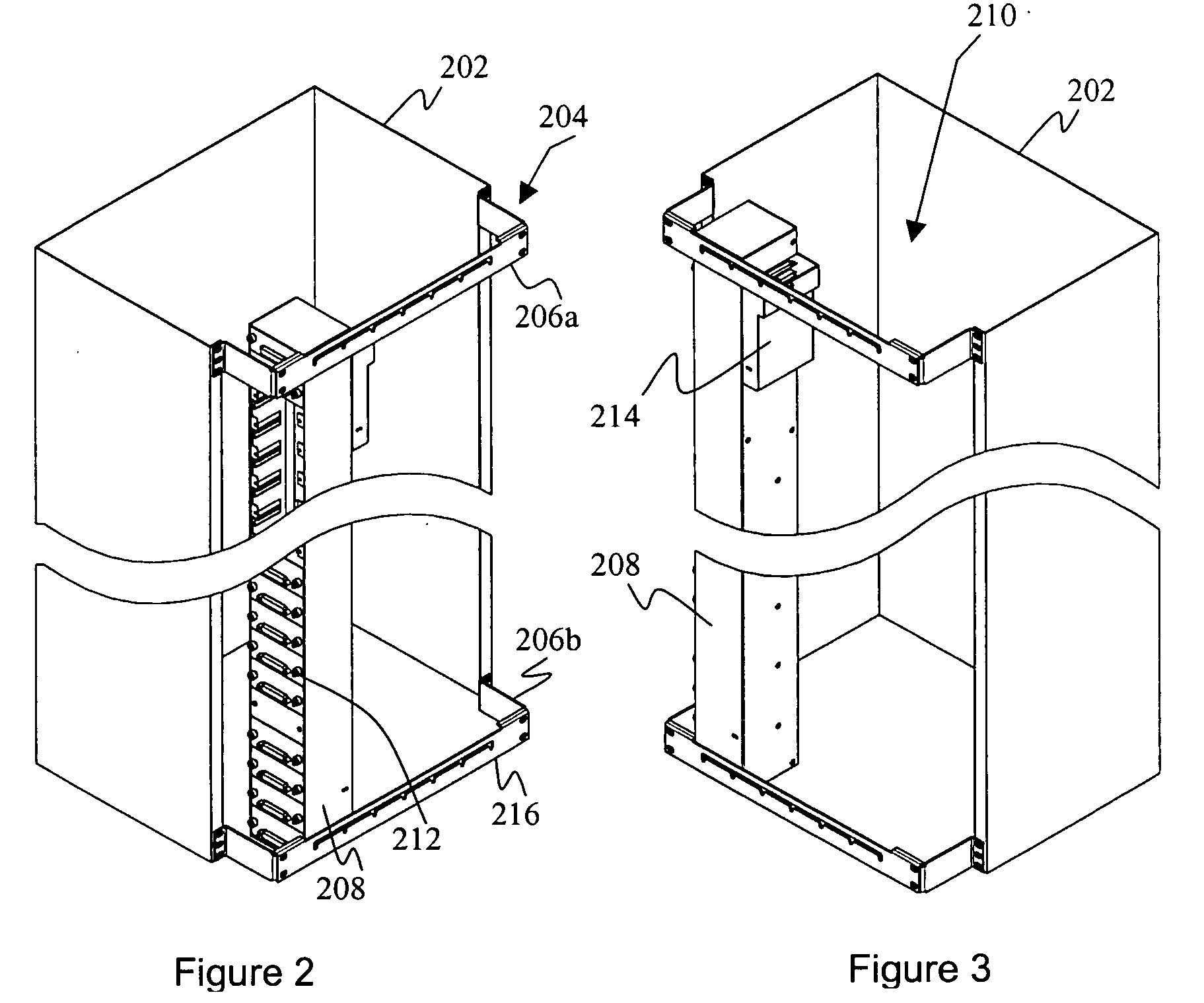
One embodiment of the invention provides a fully distributed, scaleable and modular rack architecture and management system. One feature of the invention provides device management throughout the rack system with a vertical interface column integrated into the rack cabinet. Within each rack unit (U) of the vertical interface column, the vertical interface column may deliver connectivity to a device housed within the rack cabinet thereby eliminating runs of cable typically necessary for management of such devices. The vertical interface column can be expanded as necessary to provide connectivity to more devices using hot-swappable interface modules. A rack management system allows both local and remote management access to all devices mounted in the rack cabinet and coupled to the vertical interface column. The rack management system may also access to devices mounted in other rack cabinets.

Description

CROSS REFERENCE TO RELATED APPLICATION [0001] This non-provisional United States (U.S.) patent application claims the benefit of U.S. Provisional Application No. 60 / 498,193, filed on Aug. 27, 2003 by inventors Edward Behrens, Tho Tu, Van T. Hua, and David Wang, titled “Distributed, Scalable Rack Equipment and Server Management System.”FIELD [0002] Various embodiments of the invention pertain to rack enclosure cabinets for computer and other electrical devices. More particularly, at least one embodiment of the invention relates to a rack architecture with a interface column to reduce cabling in the rack cabinet as well as centralize system management to efficiently monitor and control devices in the rack cabinet. DESCRIPTION OF RELATED ART [0003] Rack enclosure cabinets have been used to house a plurality of computers and other devices. Such rack cabinets provide a way to house a number of computers and / or other devices in a limited space. Data centers, where large numbers of compute...

Claims


Application Information

Patent Timeline
Patent Type & Authority Applications(United States)
IPC IPC(8): A47BG06F13/00H02B1/20H05K7/14
CPCG06F1/18H05K7/1492G06F1/26G06F1/189
Inventor BEHRENS, EDWARDTU, THOHUA, VAN T.WANG, DAVID
Owner CHATSWORTH PROD INC
Learn More