
Method and device for the correction of a scanned image

a scanned image and image correction technology, applied in image data processing, character and pattern recognition, instruments, etc., can solve the problems of significant problems in automatic methods of evaluating such images, distorted images, etc., and achieve the effect of reducing calculation effort, being executed very quickly and very precisely

Inactive Publication Date: 2005-03-10
OCE DOCUMENT TECH
View PDF17 Cites 40 Cited by
  • Summary
  • Abstract
  • Description
  • Claims
  • Application Information

AI Technical Summary

Benefits of technology

The present invention provides a method for automatic correction of a scanned image of a non-planar original with a constant cross-section contour that can be executed very quickly with relatively low calculation effort.
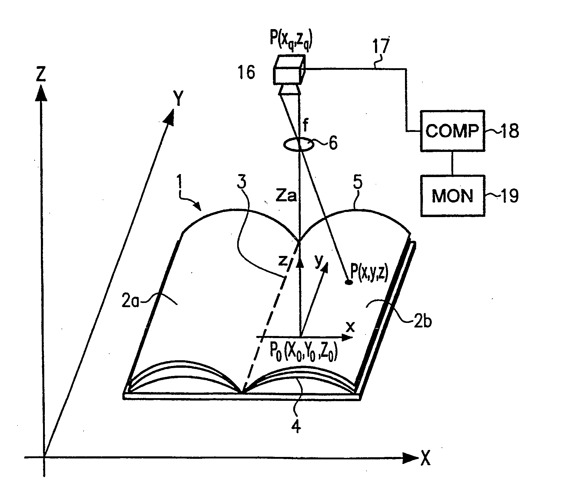
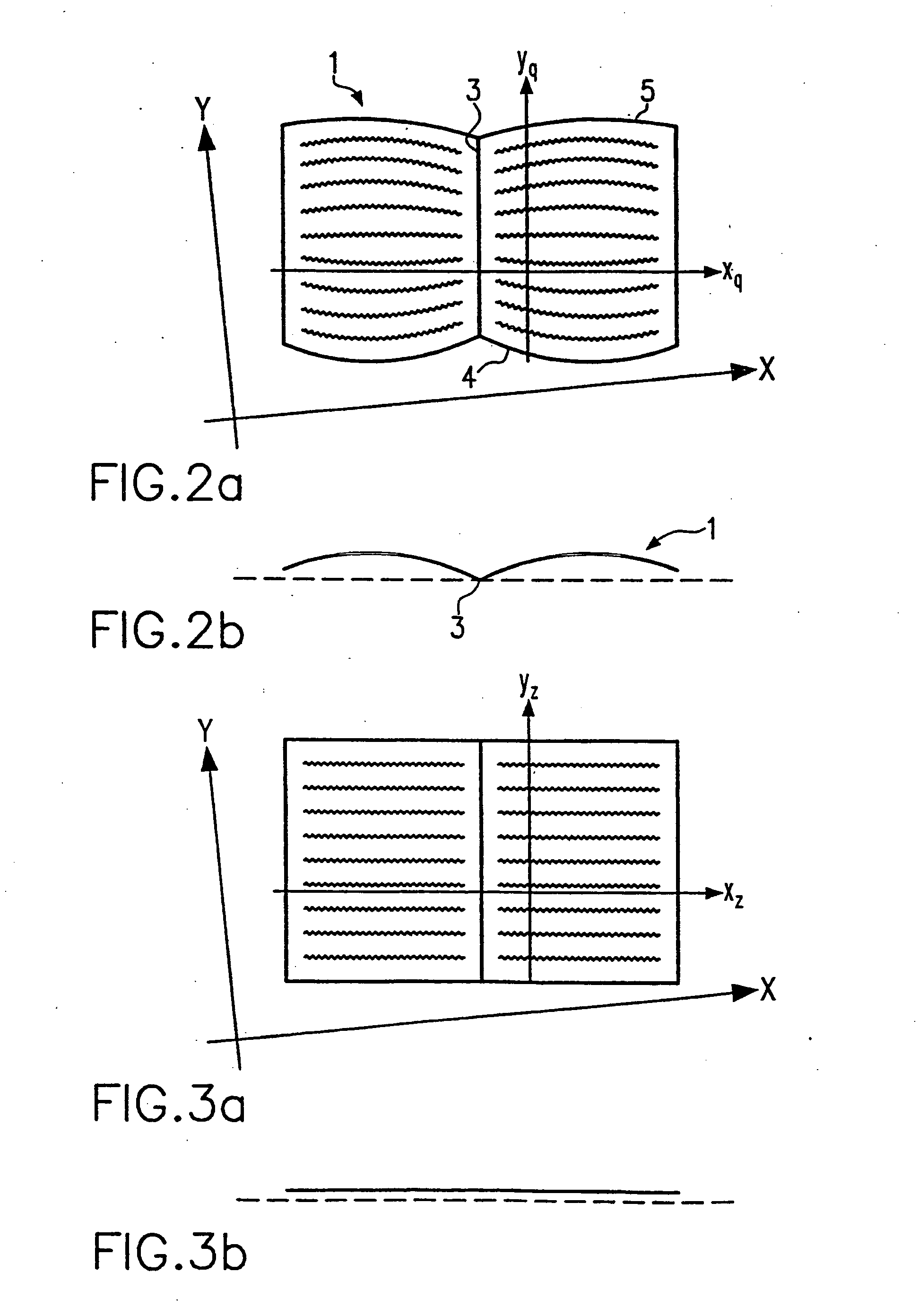
The x-dilation factor and the y-dilation factor, also referred to as extension factors or distortions of the image, depend only on the x-coordinate and not on the y-coordinate, due to the imaging or, respectively, arrangement of the source image in a Cartesian coordinate system in which one line of the source image that runs parallel to the constant cross-section contour is arranged parallel to the x-axis and using an image in which the coordinates are multiplied with corresponding dilation factors. It is hereby possible to respectively calculate a list of x-dilation factors and y-dilation factors that are respectively associated with an x-values, such that only the dilation factors are to be considered dependent on the respective x-value given the calculation of the corrected target image. The dilation factors thus exist as one-dimensional lists and not as multidimensional fields, which significantly reduces the calculation effort, whereby the method can be executed very quickly and very precisely.

Problems solved by technology

This leads to a distorted image.
This distortion of the image is both disturbing to the human viewer of this image and causes significant problems in automatic methods of evaluating such images.

Method used


Image

  • Method and device for the correction of a scanned image
  • Method and device for the correction of a scanned image
  • Method and device for the correction of a scanned image

Examples


Embodiment Construction

In a particularly advantageous embodiment of the invention, the mapping to the Cartesian coordinate system and the mapping of the points of the source image to the points of the target image or, respectively, vice versa is executed with a single calculation operation. This produces two significant advantages, namely that on the one hand the method can be executed very quickly, and on the other hand rounding errors (which can never be prevented in individual calculation operations) are reduced to a minimum. The method is hereby very precise and at the same time very fast.

In the inventive method for automatic correction of a scanned image of a non-planar original with a cross-section contour constant along one axis, the original is scanned with an objective arranged stationary. The scanned image thereby represents a source image that is mapped to a corrected target image with the following steps: mapping of the source image onto a Cartesian coordinate system, whereby a line of the...


PUM


Abstract

A method and apparatus for correcting a scanned image of a non-planar original that has a constant cross section in one direction, such as a book, provides for applying a coordinate system to the scanned image to align the coordinate system to the direction with the constant cross section. The scanned image is imaged onto a target image, or vise versa, using aspect factors or dilation factors. A single calculation is possible to map an image point from the scanned image to the target image and thereby remove the distortion of the non-planar original.

Description

BACKGROUND OF THE INVENTION 1. Field of the Invention The present invention relates generally to a method to correct a scanned image of a non-planar original image that has a constant cross-section contour. 2. Description of the Related Art In the optical sampling or, respectively, scanning of contoured objects (such as, for example, books), the surface to be scanned is not situated in a single plane. This leads to a distorted image. This distortion of the image is both disturbing to the human viewer of this image and causes significant problems in automatic methods of evaluating such images. To correct such images, analytical methods have been known for a long time that calculate the corrected image points from inverse collinearity equations. These collinearity equations are, for example, are shown in chapter 4 of the book “Nahbereichsphotogrammetrie: Grundlagen, Methoden, Anwendungen”, by Thomas Luhmann, Herbert Wichmann Verlag, published 2000, ISBN 3-87907-321-X. To simplif...

Claims


Application Information

Patent Timeline
Patent Type & Authority Applications(United States)
IPC IPC(8): G06T3/00
CPCG06T3/0031G06T3/06
Inventor FREI, BERNHARD
Owner OCE DOCUMENT TECH
Learn More