Joint simulator testing machine

a simulator and simulator technology, applied in the field of joint simulators, can solve the problems of increasing the cost of spinal implants, retrofitting or completely redesigning such machines for use with spinal implants, increasing the cost, and in some cases, the size, the device is costly and complicated in function for many uses, and the effect of increasing the cos

Inactive Publication Date: 2005-03-17
HOWMEDICA OSTEONICS CORP
View PDF15 Cites 21 Cited by
  • Summary
  • Abstract
  • Description
  • Claims
  • Application Information

AI Technical Summary

Benefits of technology

[0010] The head adapter serves as an extension of the second component (e.g., the ball), in that loading of the head adapter in turn loads the second component, and an articulation of the head adapter effects an angularly and positionally (e.g., translation movement as opposed to angulation or rotation) equivalent articulation of the second component. Thus, the head adapter is positioned and configured to engage the second component (e.g., the ball) of the test device. In the illustrated embodiment, the head adapter includes a cap and a stem that extends downwardly from the cap and has a lower end coupled to an engagement surface, e.g., a flat upper surface, of the ball. Preferably, the longitudinal axis of the stem is aligned with the center of rotation of the ball. Also preferably, the stem and ball are fixed to one another in this configuration and / or coupled in this configuration so that relative rotation therebetween is prevented during operation of the testing machine as described below.

Problems solved by technology

Moreover, many joint testing devices have been developed specifically for use with hip and knee joints, and in that respect are unsuitable for use with the growing number of spinal implants.
The need to retrofit or completely redesign such machines for use with spinal implants increases the cost, and in some cases, the size.
While utilizing newer technologies to increase speed and minimize size, these device are nevertheless costly and complicated in function for many uses.

Method used


Image

  • Joint simulator testing machine
  • Joint simulator testing machine
  • Joint simulator testing machine

Examples


Embodiment Construction

[0029] While the invention will be described more fully hereinafter with reference to the accompanying drawings, it is to be understood at the outset that persons skilled in the art may modify the invention herein described while achieving the functions and results of the invention. Accordingly, the descriptions that follow are to be understood as illustrative and exemplary of specific structures, aspects and features within the broad scope of the invention and not as limiting of such broad scope. Like numbers refer to similar features of like elements throughout.

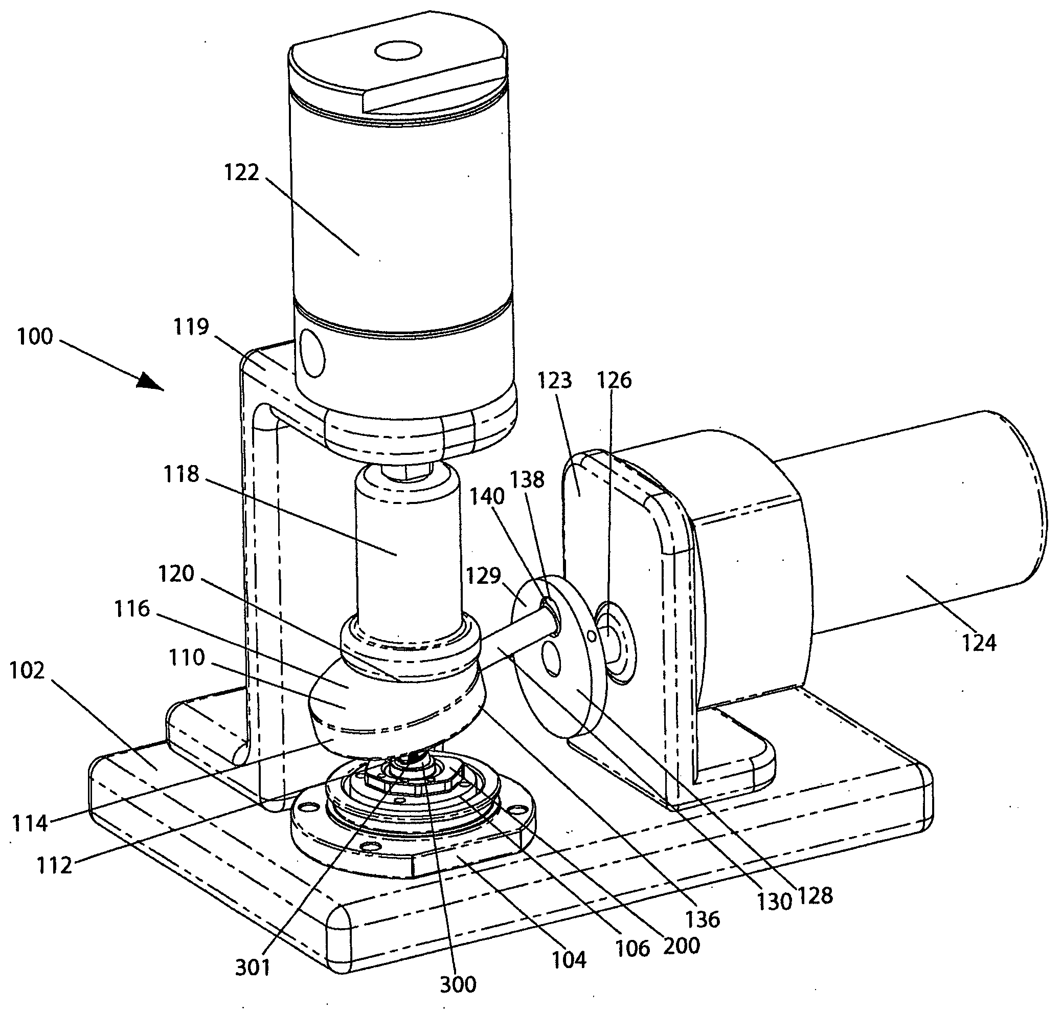
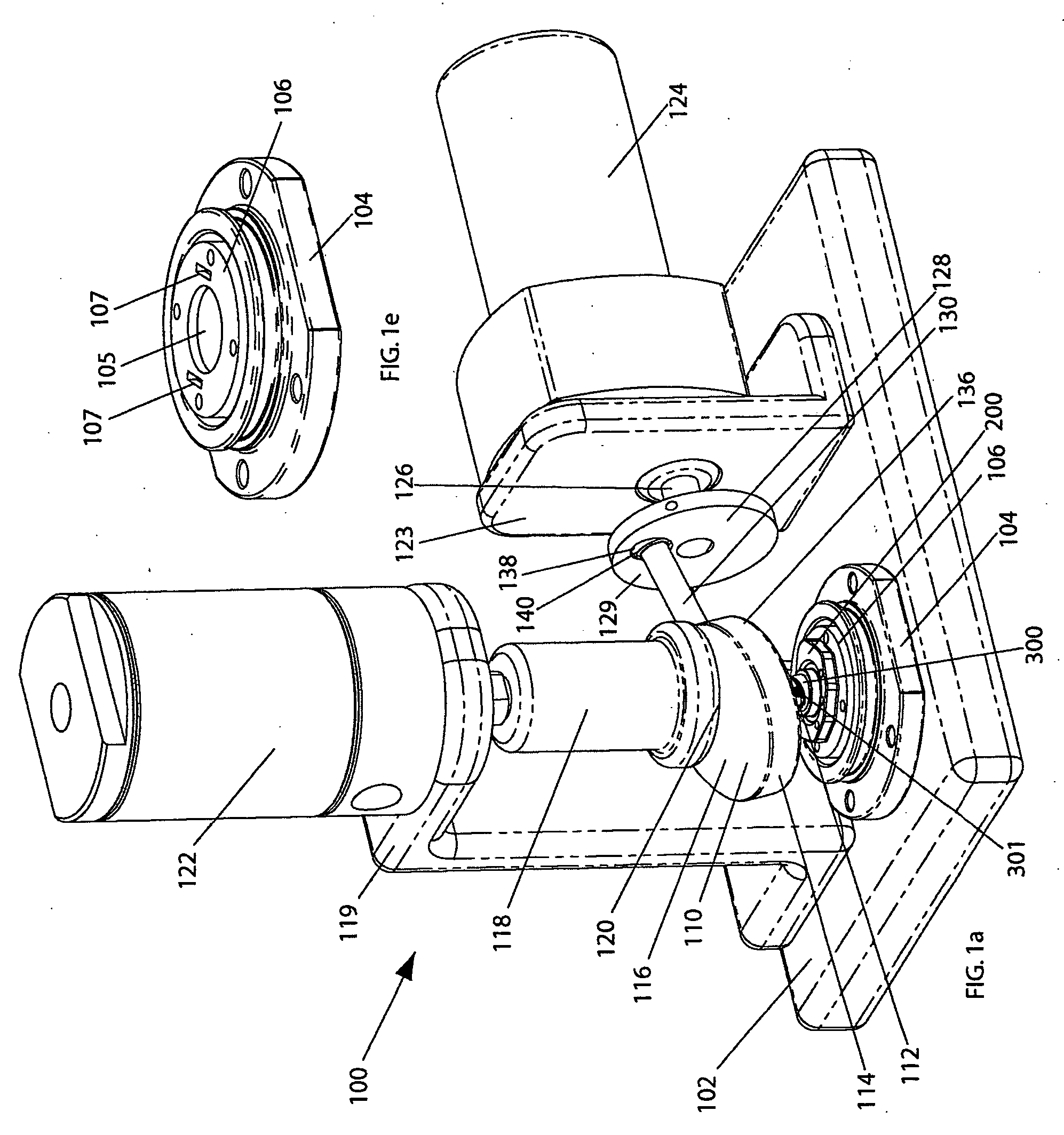
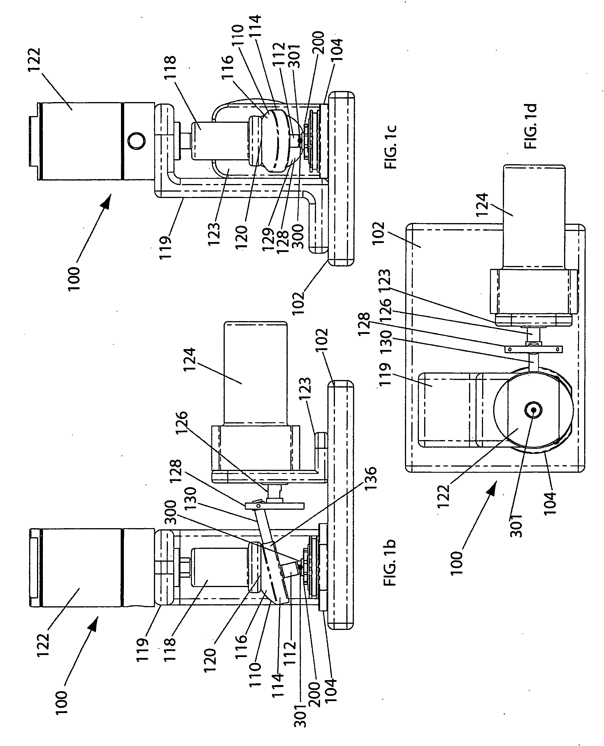
[0030] Referring now to FIGS. 1a-d, a preferred embodiment of a testing apparatus of the present invention is shown in perspective, front, side, and top views, respectively. The illustrated testing apparatus 100 is provided primarily for use in evaluating performance characteristics of a joint, and more particularly for testing components of a joint in articulation relative to one another under a load. Joints suitable for ...


PUM

PropertyMeasurementUnit
angleaaaaaaaaaa
anglesaaaaaaaaaa
angleaaaaaaaaaa

Abstract

An apparatus for testing an implant having first and second components coupled together by an articulating ball and socket joint includes a support structure in contact with the first component of the implant for supporting said implant, an adapter coupled to the second component of the implant, and a load assembly in contact with the adapter for applying a load onto a semispherical surface of the adapter. The apparatus includes a drive assembly coupled with the adapter having a first drive shaft having a first end connected with a center of a rotatable wheel and a second drive shaft having a first end connected with an outer region of the wheel and a second end connected to the adapter. The second drive shaft has a longitudinal axis that is at an angle relative to the longitudinal axis of the first drive shaft. In operation, rotation of the first drive shaft about the longitudinal axis thereof causes articulating movement of the adapter, which in turn causes articulating movement of the first and second components of the implant under load.

Description

CROSS REFERENCE TO RELATED APPLICATIONS [0001] The present application is a continuation of U.S. application Ser. No. 10 / 384,981 filed Mar. 10, 2003, the disclosure of which is hereby incorporated herein by reference.BACKGROUND OF THE INVENTION [0002] This invention relates generally to joint simulators for testing purposes, and more specifically to joint simulators for testing components of a joint in articulation relative to one another under a load. [0003] Artificial or prosthetic devices for replacing defective joints in humans have been the subject of extensive research and development efforts for many years, especially with regard to hip and knee joints, and more recently with spinal joints. In the design of such devices, it is advisable to subject the components of each new design to static and dynamic testing. Such testing is necessary to ensure that a particular design does not fail prematurely. Thus, a need exists within the medical equipment industry to assess the enduran...

Claims


Application Information

Patent Timeline
Patent Type & Authority Applications(United States)
IPC IPC(8): A61F2/44A61F2/46G01M99/00G01N3/00G01N3/02G01N3/56
CPCA61F2/4425A61F2/468G01N3/02G01N2203/0246G01N3/56G01N2203/0089G01N3/32
Inventor ZUBOK, RAFAILERRICO, JOSEPH P.DUDASIK, MICHAEL W.
Owner HOWMEDICA OSTEONICS CORP
Why Eureka
Try Eureka