Image forming apparatus and image forming method

a technology of image forming apparatus and forming method, which is applied in the direction of electrographic process apparatus, instruments, optics, etc., can solve problems such as adversely affecting images, and achieve the effect of sufficiently and efficiently eliminating toners and forming clear images

Active Publication Date: 2005-03-31
KK TOSHIBA +1
View PDF10 Cites 20 Cited by
  • Summary
  • Abstract
  • Description
  • Claims
  • Application Information

AI Technical Summary

Benefits of technology

[0007] It is an object of the present invention to provide an image forming apparatus and an image forming method capable of continuously forming clear images by sufficiently and efficiently eliminating toners mixed with paper dust or other color toners mixed in a developing device of an image forming apparatus for forming images using two-component developer and utilizing a cleaner-less process.

Problems solved by technology

However, paper powder of transfer materials and peripheral dust are also recovered, causing such a trouble that they are mixed into developer in a developing device.
However, when paper dust mixed in developer is increasing, even when dispersed in a developing device, developer deteriorated and in mixed colors may adversely affect an image.

Method used


Image

  • Image forming apparatus and image forming method
  • Image forming apparatus and image forming method
  • Image forming apparatus and image forming method

Examples


third embodiment

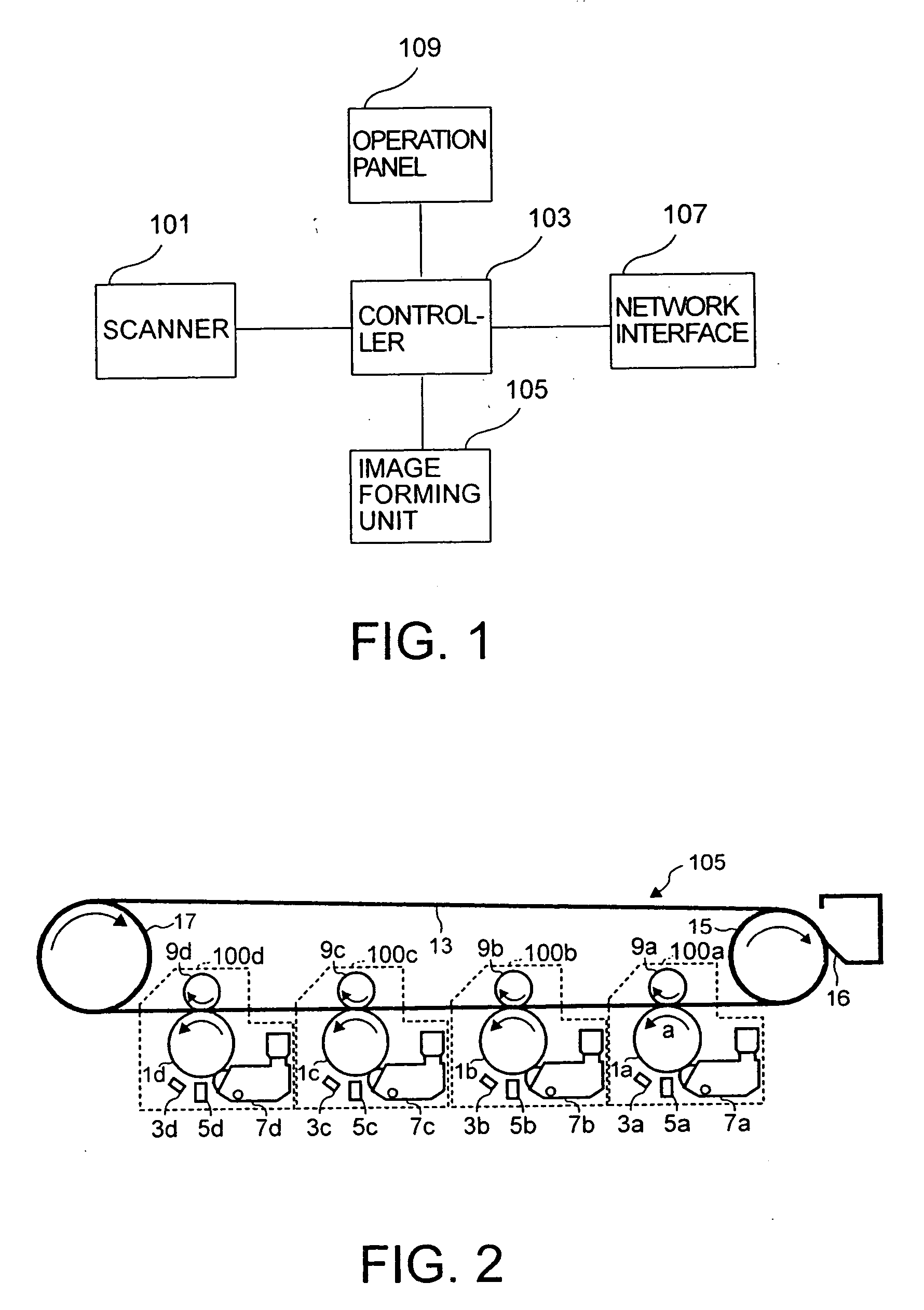
[0081] In the third embodiment, an amount of toner containing paper dust and other color toners mixing into second to fourth processing units 100b to 100d is decided based on a difference between a toner area formed by an upstream processing unit and a toner image area formed by it's own.

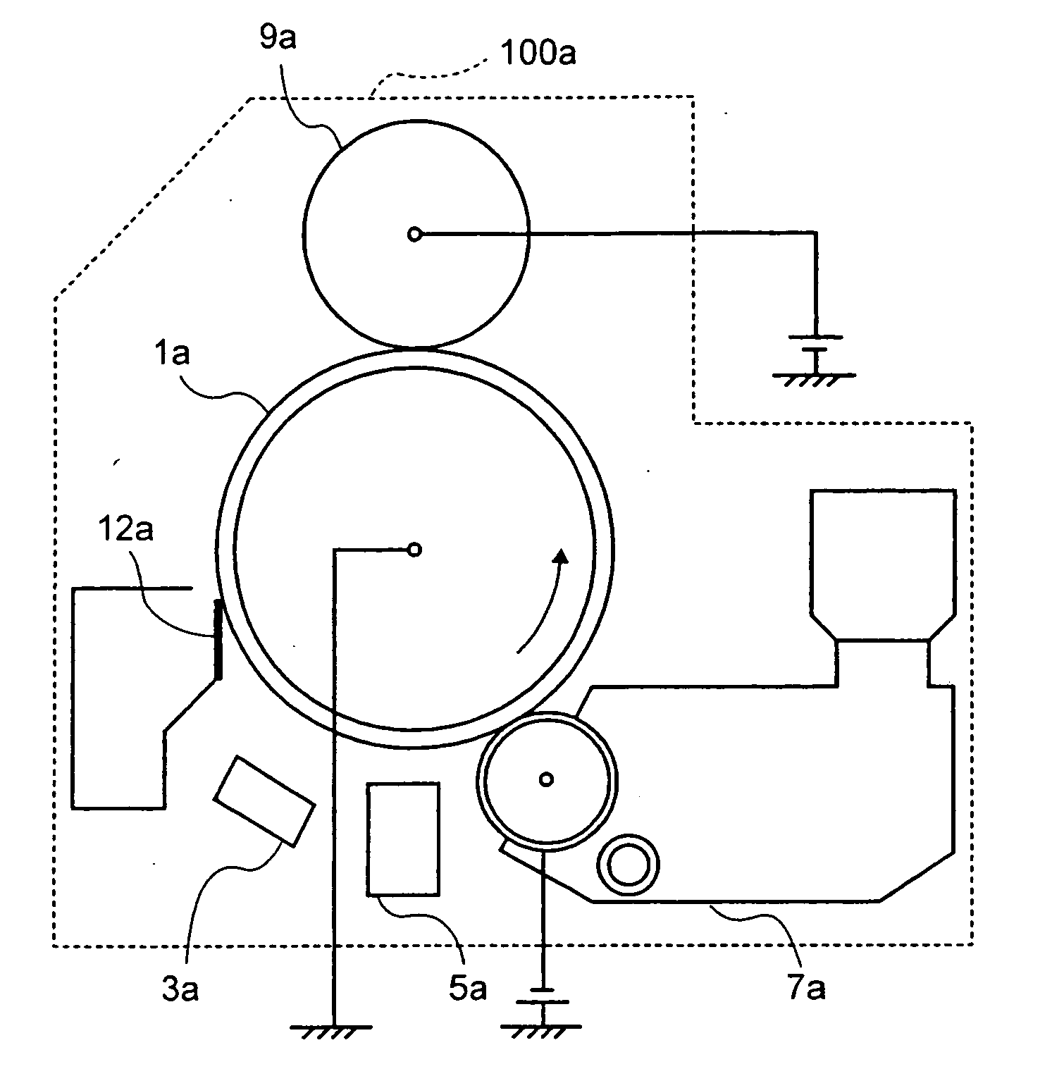
[0082] This will be explained taking second processing unit 100b as an example. First, a area of a toner image formed in first processing unit 100a. This area may be obtained by directly taking a picture using a CCD or other means and also, from an electrostatic latent image formed on photosensitive drums 1b to 1d.

[0083] A area of a toner image that is to be formed in second processing unit 100b is obtained from a area of an electrostatic latent image drawn by exposure unit 5b on photosensitive drum 1b.

[0084] As an area of toner images formed by first processing unit 100a is wider, toner to get into second processing unit 100b of a developing device increases more in quantity. In portions where t...

fourth embodiment

[0087] In the fourth embodiment, a high density toner image such as a solid image is developed on the photosensitive drum when an image is not formed and mixed color toners are carried out efficiently in addition to the discharging of developer by a relevant processing unit itself based on a toner density.

[0088] At this time, for example, when toner is discharged after forming a solid image in second processing unit 100b, in third processing unit 100c and fourth processing unit 100d at the downstream side, toner is transferred inversely to photosensitive drums 1c and 1d from a toner image formed in second processing unit 100b. In order to prevent this, the reverse transfer of toner is suppressed by reducing transferring current given to transfer units 9c and 9d of third processing unit 100c and fourth processing unit 100d when forming a solid mage for the purpose of discharging toner in second processing unit 100b.

[0089] Thus, the color toner mixing to third and fourth processing ...

fifth embodiment

[0090] Some of toners transferred inversely from a first formed toner image may be in the negatively charged state. In the fifth embodiment, a mechanism to prevent negatively charged inversely transferred other color toners from mixing in the developing device will be described.

[0091] In this embodiment, a processing unit 100e shown in FIG. 18 will be used for second processing unit 100b shown in FIG. 1.

[0092] Processing unit 100e is composed of a photosensitive drum 1e, a main charger 3e, an exposure unit 5e, a developing device 7e, a transfer unit 9e, an elastic roller 100e, a brush roller 102e, and a contract member 204e.

[0093] Elastic roller 200e applied with voltage of about −199V is kept in contact with photosensitive drum 1e between the transfer position and the charging position of photosensitive drum 1e as shown in FIG. 18. Further, brush roller 202e applied with +250V is brought in contact with this elastic roller 200e.

[0094] Potential at the portion of photosensitive ...


PUM


Abstract

In an image forming apparatus using the cleaner-less processing, a developer vent is provided to a developing device so as to discharge paper dust mixing in the developing device together with developer comprising carrier and toner or carrier only through the developer vent, when removing residual toner.

Description

CROSS-REFERENCE TO RELATED APPLICATIONS [0001] This application is based upon and claims the benefit of priority from prior Japanese Patent Application No. 2003-340902, filed Sep. 30, 2003; the entire contents of which are incorporated herein by reference. BACKGROUND OF THE INVENTION [0002] 1. Field of the Invention [0003] The present invention relates to an image forming apparatus that uses two-component developer comprising toner and carrier and an image forming method. [0004] 2. Description of the Related Art [0005] An image forming technology utilizing a cleaner-less process is widely known and practically used. In this cleaner-less process, a developing device recovers residual toner on a photosensitive drum. However, paper powder of transfer materials and peripheral dust are also recovered, causing such a trouble that they are mixed into developer in a developing device. As a countermeasure to this problem, a technology to get a clear image without being affected by powder of ...

Claims


Application Information

Patent Timeline
Patent Type & Authority Applications(United States)
IPC IPC(8): G03G15/08G03G15/00G03G21/00G03G21/10
CPCG03G2221/0042G03G21/0064
Inventor WATANABE, TAKESHIHIROKI, MASASHITAKAHASHI, MASASHI
Owner KK TOSHIBA
Why Eureka
Try Eureka