Apparatus for controlling the pressure of gas by bubbling through a liquid, such as bubble CPAP

a technology of apparatus and gas, which is applied in the direction of valves, respirators, operating means/releasing devices, etc., can solve the problems of increased wear and tear of ventilators, intermediate and fine adjustments, 5.5 centimeters of cpap, etc., and achieves more diligence for reliability. , the effect of cpap

Inactive Publication Date: 2005-04-07
JACOBS HARRIS C +1
View PDF11 Cites 45 Cited by
  • Summary
  • Abstract
  • Description
  • Claims
  • Application Information

AI Technical Summary

Benefits of technology

[0019]FIG. 1 is a schematic diagram of a conventional prior art system for effecting bubble CPAP;

Problems solved by technology

Use of a mechanical ventilator is quite reliable, but increases wear and tear on the ventilator.
As will be appreciated by those skilled in the art, while it is possible using a conventional bubble CPAP set-up like that shown in FIG. 1 to place an infant on 5 centimeters of CPAP or 6 centimeters of CPAP, intermediate and finer adjustments, e.g., 5.5 centimeters of CPAP, are not practical.
Moreover, the use of bubble CPAP requires more diligence for reliability.
Specifically, no reliable method for insuring the depth of insertion of the ventilator tube in the liquid is available.
Hence the tube may slip in or out inadvertently which changes the pressure in the ventilator tubing to the infant.

Method used


Image

  • Apparatus for controlling the pressure of gas by bubbling through a liquid, such as bubble CPAP
  • Apparatus for controlling the pressure of gas by bubbling through a liquid, such as bubble CPAP
  • Apparatus for controlling the pressure of gas by bubbling through a liquid, such as bubble CPAP

Examples


Embodiment Construction

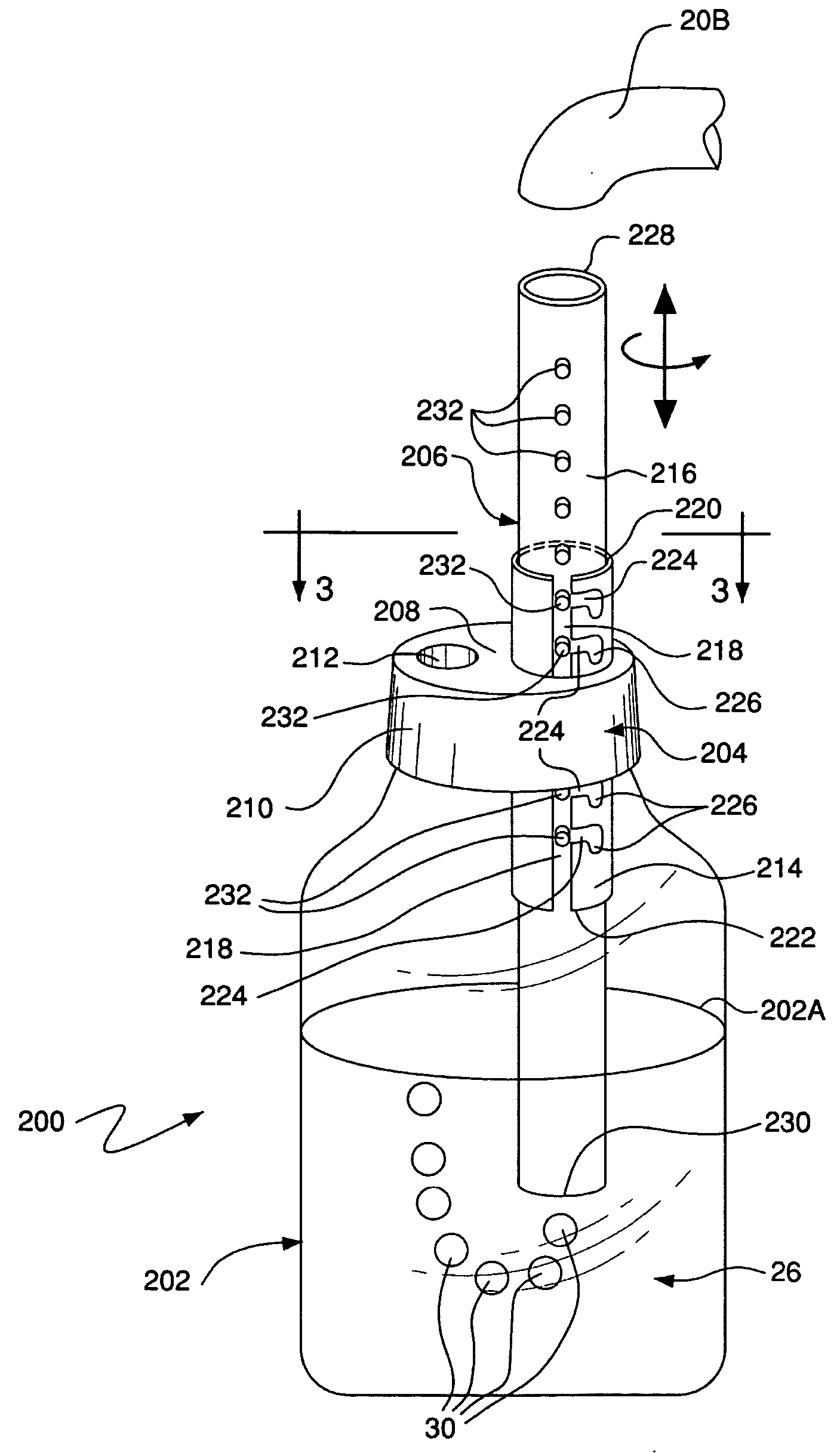
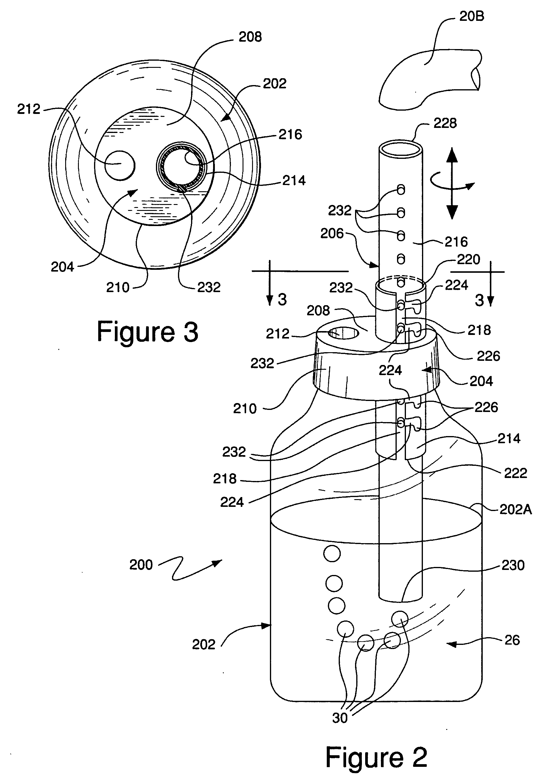
[0027] Referring now to the various figures of the drawing wherein like reference characters refer to like parts, there is shown at 200 and 300 in FIGS. 2 and 4, respectively, exemplary embodiments of apparatus for controlling pressure of a gas in a system that depends on the pressure being produced by bubbling the gas through a liquid constructed in accordance with this invention. It should be noted at this juncture that while the apparatus 200 and 300 are particularly suited for effecting bubble CPAP, they can be used of any other application involving controlling pressure of a gas in a system that depends on the pressure being produced by bubbling the gas through a liquid.

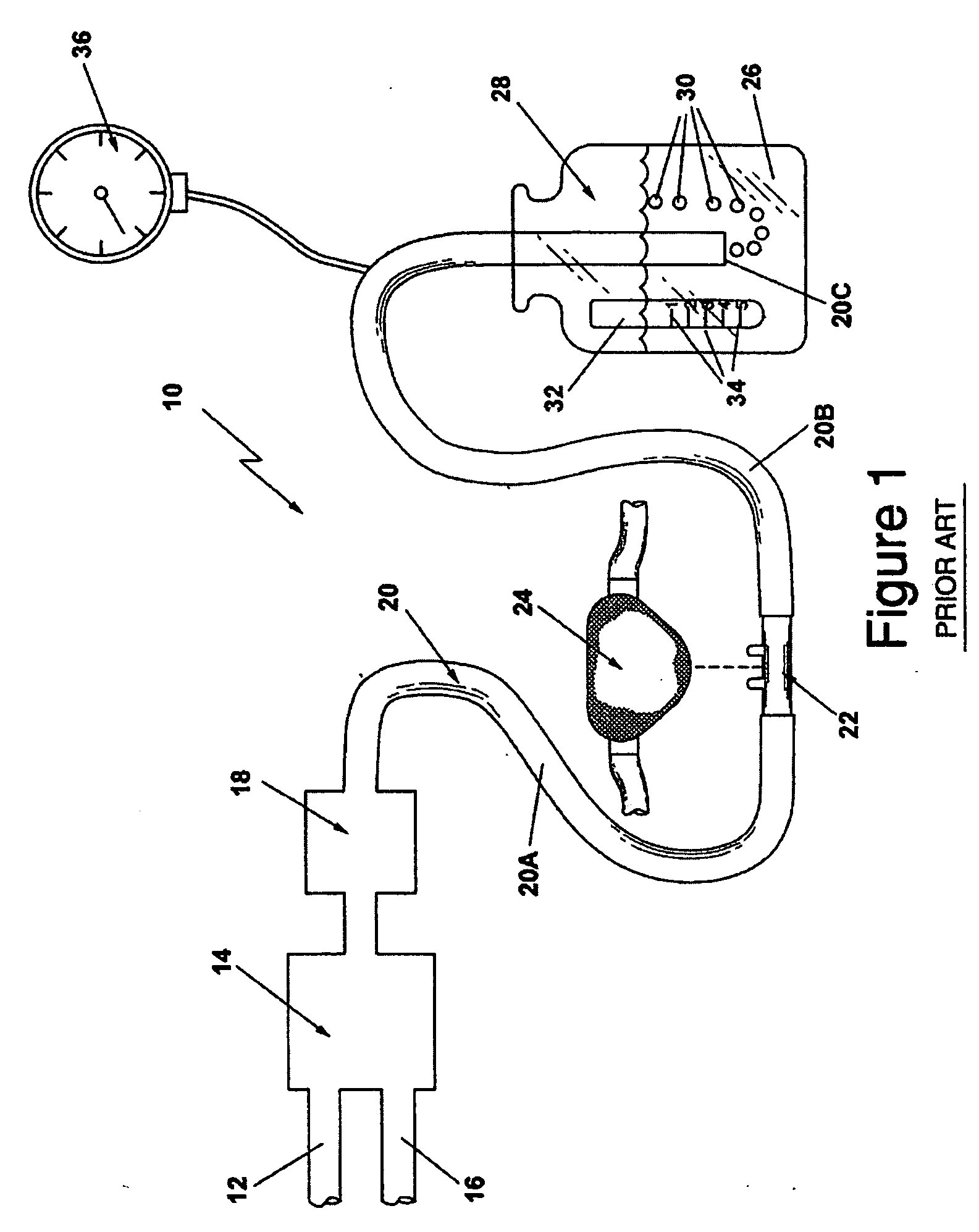
[0028] Turning now to FIGS. 2 and 3, the details of the construction and operation of the apparatus 200 will now be described. Before doing that, it should be pointed out that if the apparatus 200 is to be used for bubble CPAP, it can be connected in a system like that shown in FIG. 1 in lieu of the bottle 28 a...


PUM


Abstract

Apparatus for effecting bubble CPAP. The apparatus includes a hollow vessel holding a liquid, a cap, and a positionable tube assembly. The positionable tube assembly comprises a guide tube and a positionable tube. The positionable tube is arranged to have a gas introduced through it and is located within the guide tube. The positionable tube is arranged to be slid to various discrete longitudinal positions with respect to the guide tube and to be held in any one of those discrete positions against accidental displacement so that the lower free end of the positionable tube is held at a desired position below the surface of the liquid.

Description

CROSS-REFERENCE TO RELATED APPLICATIONS [0001] This application claims priority from our provisional U.S. Patent Application Ser. No. 60 / 507,715, filed on Oct. 1, 2003, and provisional U.S. Patent Application No. ASN 60 / 576,674, filed on Jun. 3, 2004.STATEMENT REGARDING FEDERALLY SPONSORED RESEARCH OR DEVELOPMENT [0002]“Not Applicable”INCORPORATION-BY-REFERENCE OF MATERIAL SUBMITTED ON A COMPACT DISK [0003]“Not Applicable”SPECIFICATION BACKGROUND OF THE INVENTION [0004] 1. Field of Invention [0005] This invention relates generally to apparatus for controlling pressure of a gas in a system that depends on the pressure being produced by bubbling the gas through a liquid, and more particularly to apparatus for effecting bubble continuous positive airway pressure (CPAP). [0006] 2. Description of Related Art [0007] Nasal Continuous Positive Airway Pressure (NCPAP) is a well-known technique for providing respiratory support to newborn term and preterm infants with respiratory distress req...

Claims


Application Information

Patent Timeline
Patent Type & Authority Applications(United States)
IPC IPC(8): A61M16/06A61M16/20G05D16/04
CPCA61M16/0666G05D16/04A61M2205/3348A61M16/20Y10T137/4643A61M16/201
Inventor JACOBS, HARRIS C.DEMICHIEL, LOUIS S.
Owner JACOBS HARRIS C
Why Eureka
Try Eureka