Display rack and hook combination

a technology of display racks and hooks, applied in the field of display racks and hook combinations, can solve the problems of firm support and stabilization of display hooks, and serious problems in the display rack ar

Inactive Publication Date: 2005-04-07
OBRIEN PAUL J
View PDF6 Cites 39 Cited by
  • Summary
  • Abstract
  • Description
  • Claims
  • Application Information

AI Technical Summary

Benefits of technology

[0009] It is an object of this invention to provide a display rack and hook combin...

Problems solved by technology

Although this arrangement is quite effective, this rack uses a hook that could be dislodged when a product is removed from suspension from the hook.
It can be seen f...

Method used


Image

  • Display rack and hook combination
  • Display rack and hook combination
  • Display rack and hook combination

Examples


Embodiment Construction

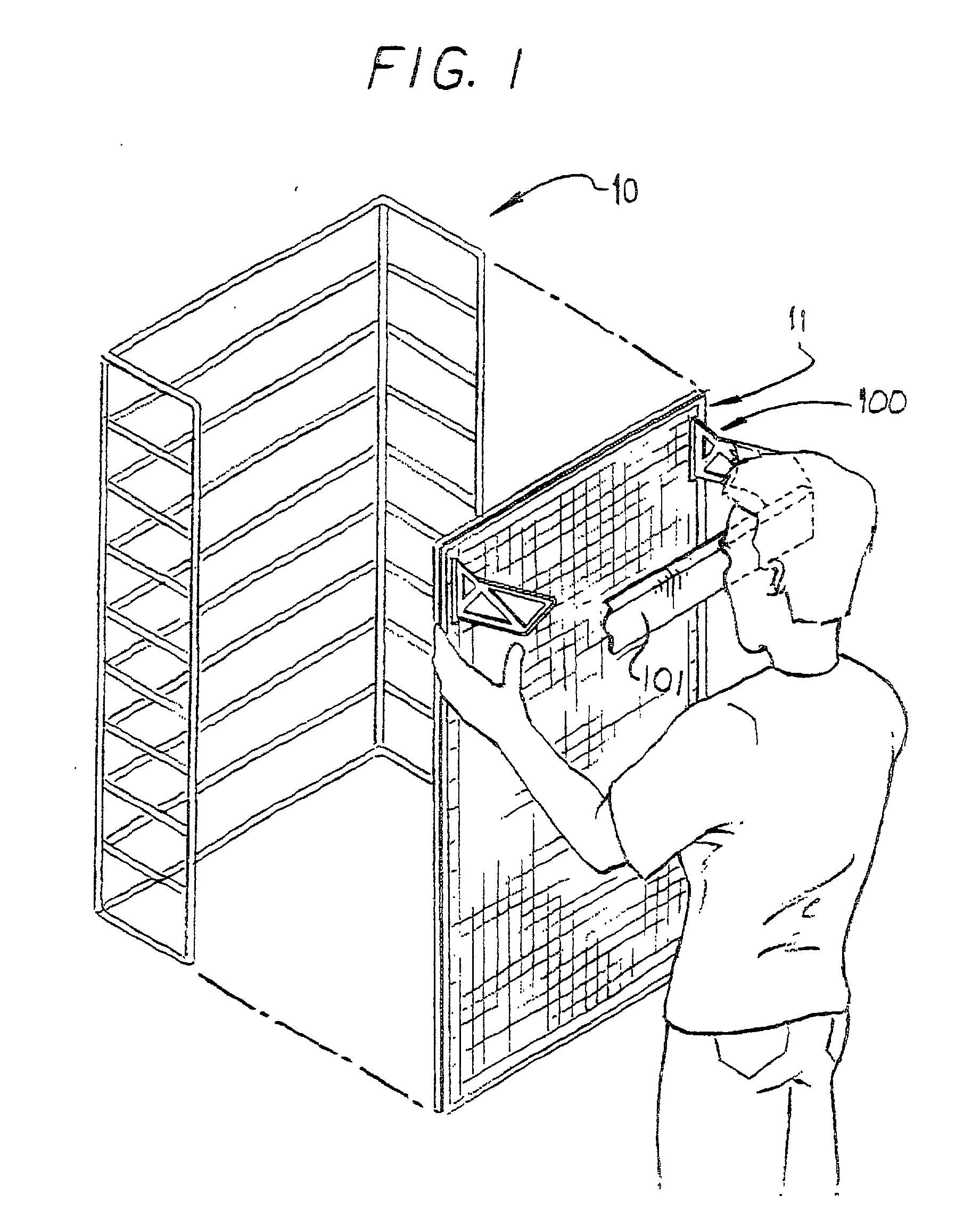
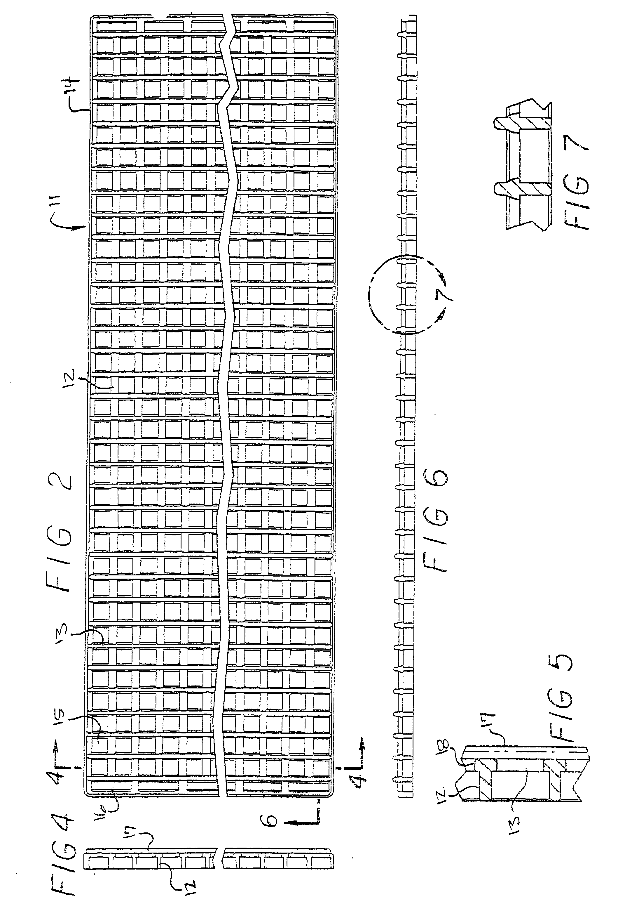
[0054] Referring now to FIG. 1 of the drawing, a pre-existing self supporting wire frame 10 is shown that may be disposed in a retail establishment or the like. A display rack 11 is about to be mounted on to frame 10. The rack 11 alone is shown in FIG. 2. This is the front view of rack 11; the rear view of rack 11 is shown in FIG. 3.

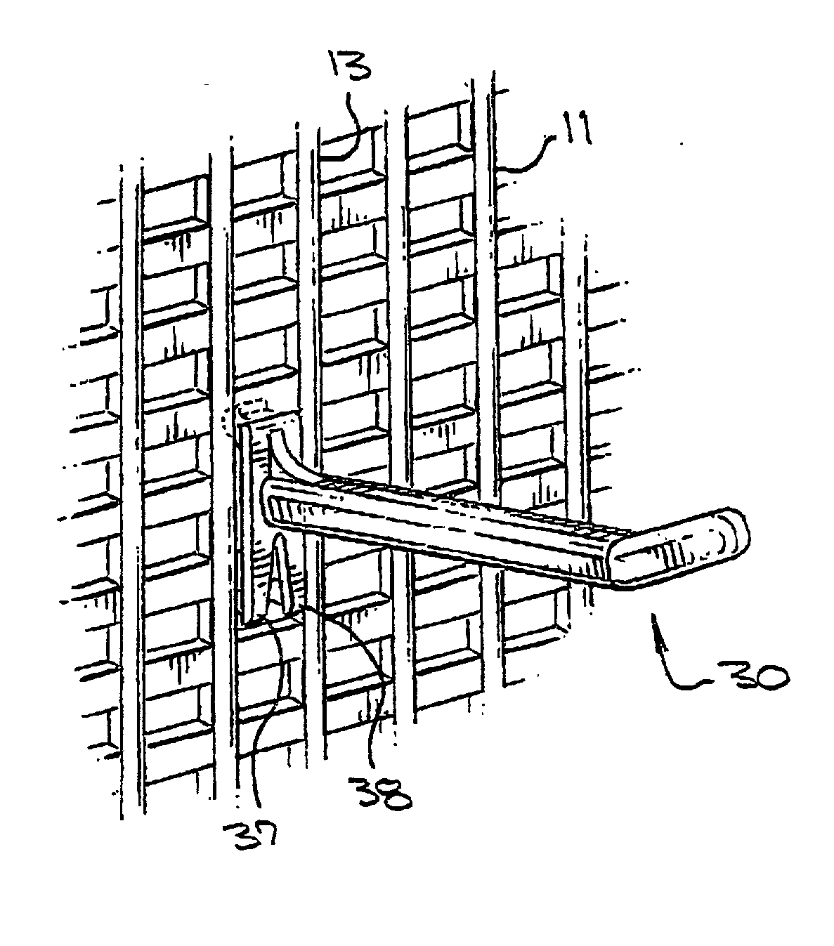
[0055] As seen in FIGS. 2, 4, and 5, rack 11 is comprised of a plurality of horizontally extending spaced ribs 12 intersected by a plurality of vertically extending spaced ribs 13. These ribs 12, 13 are enclosed by a peripheral frame 14. These ribs 12, 13 form a plurality of spaced slots 15 for receiving article bearing hooks therein, as will be discussed. On opposite sides of rack 11, that is, on the right and left sides of rack 11 as seen in FIG. 2, a plurality of elongated slots 16, longer and narrower than slots 15, are provided. This may be accomplished by narrowing the spacing between left and right side frame portions 17, 18, respectively, and th...


PUM


Abstract

A display rack and hook combination comprising a rack hung on a pre-existing wire frame. The rack has a plurality of spaced slots therein in horizontally and vertically aligned rows. Support fixtures having products suspended therefrom may be inserted into these slots. The support fixtures are of various shapes and have face places configured to snap into the slots and hold the fixtures in a firm and stabilized manner so products can be hung therefrom.

Description

BACKGROUND OF THE INVENTION [0001] 1. Field of the Invention [0002] The invention relates to display systems; and more particularly, to display racks and hook combinations including racks having display hooks mounted thereon on which products are suspended. [0003] 2. Related Art [0004] Display racks that are set up in retail stores or the like at the point of sale are well known. Such racks generally are self standing units having a back wall or the like with a plurality of spaced holes or openings into which one end of a support hook is inserted. The hook then extends outwardly from the wall, having an elongated portion for extending through an opening in a display card or the like. A product to be displayed is mounted on the card and, in this manner, a plurality of such products may be displayed to the public at the point of sale. Of course, any suitable product having means allowing it to be suspended from such hooks may be so mounted. [0005] In U.S. Pat. No. 4,671,417, there is ...

Claims


Application Information

Patent Timeline
IPC IPC(8): A47F5/08
CPCA47F5/0823
Inventor O'BRIEN, PAUL J.
Owner OBRIEN PAUL J
Why Eureka
Try Eureka