

Switch having resilient operating section
- Summary
- Abstract
- Description
- Claims
- Application Information
AI Technical Summary
Benefits of technology
Problems solved by technology
Method used
Image

Examples
Embodiment Construction
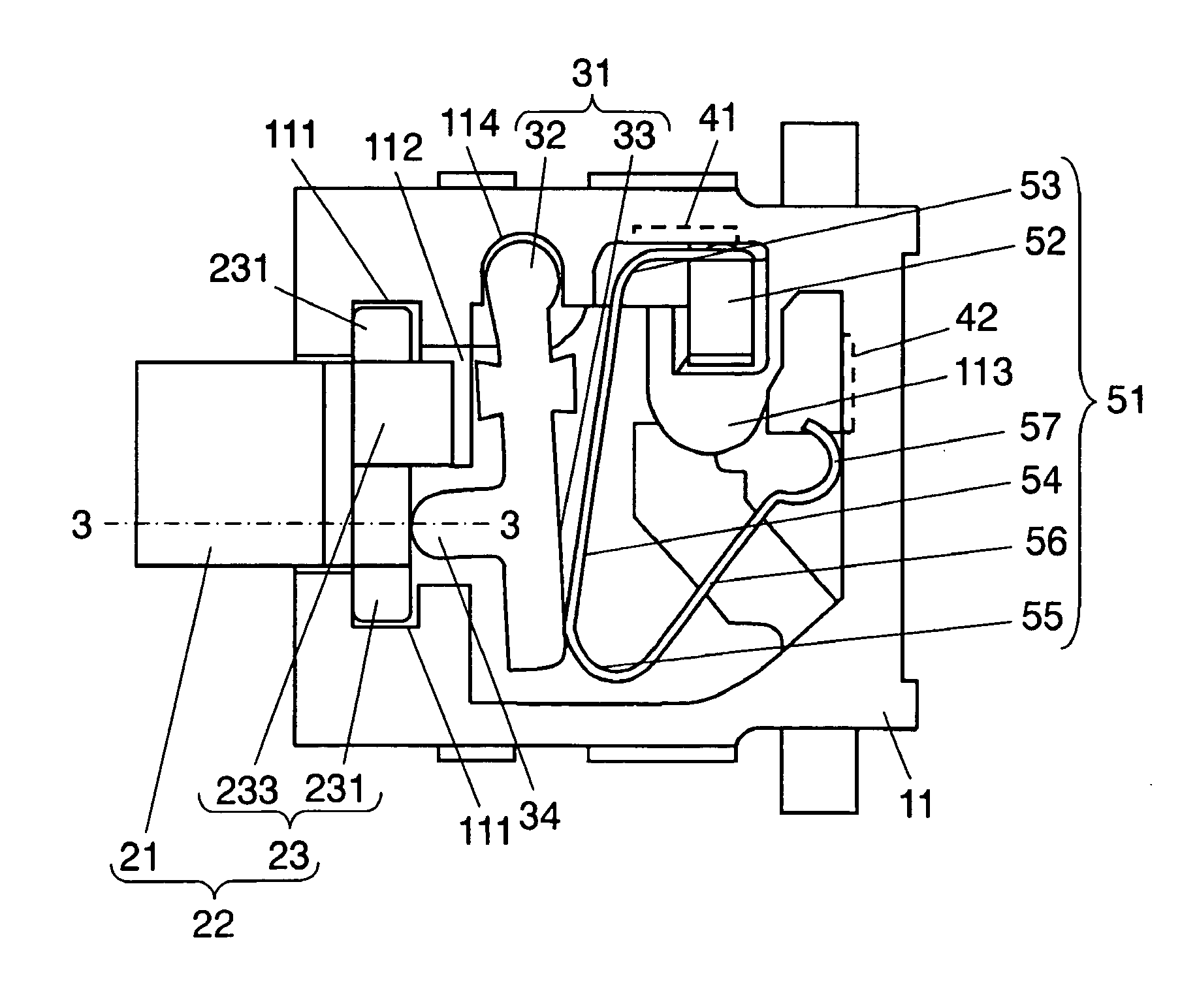
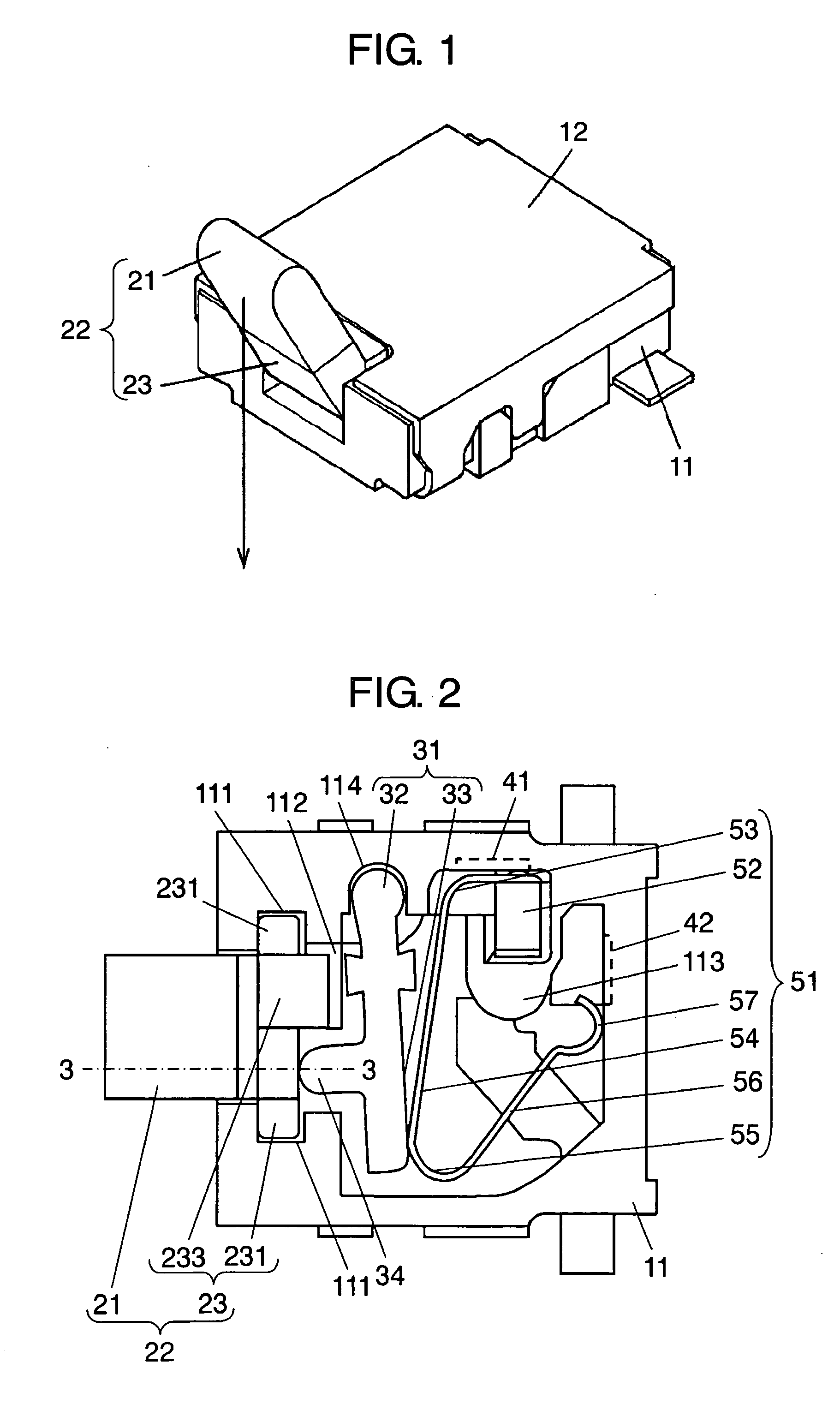
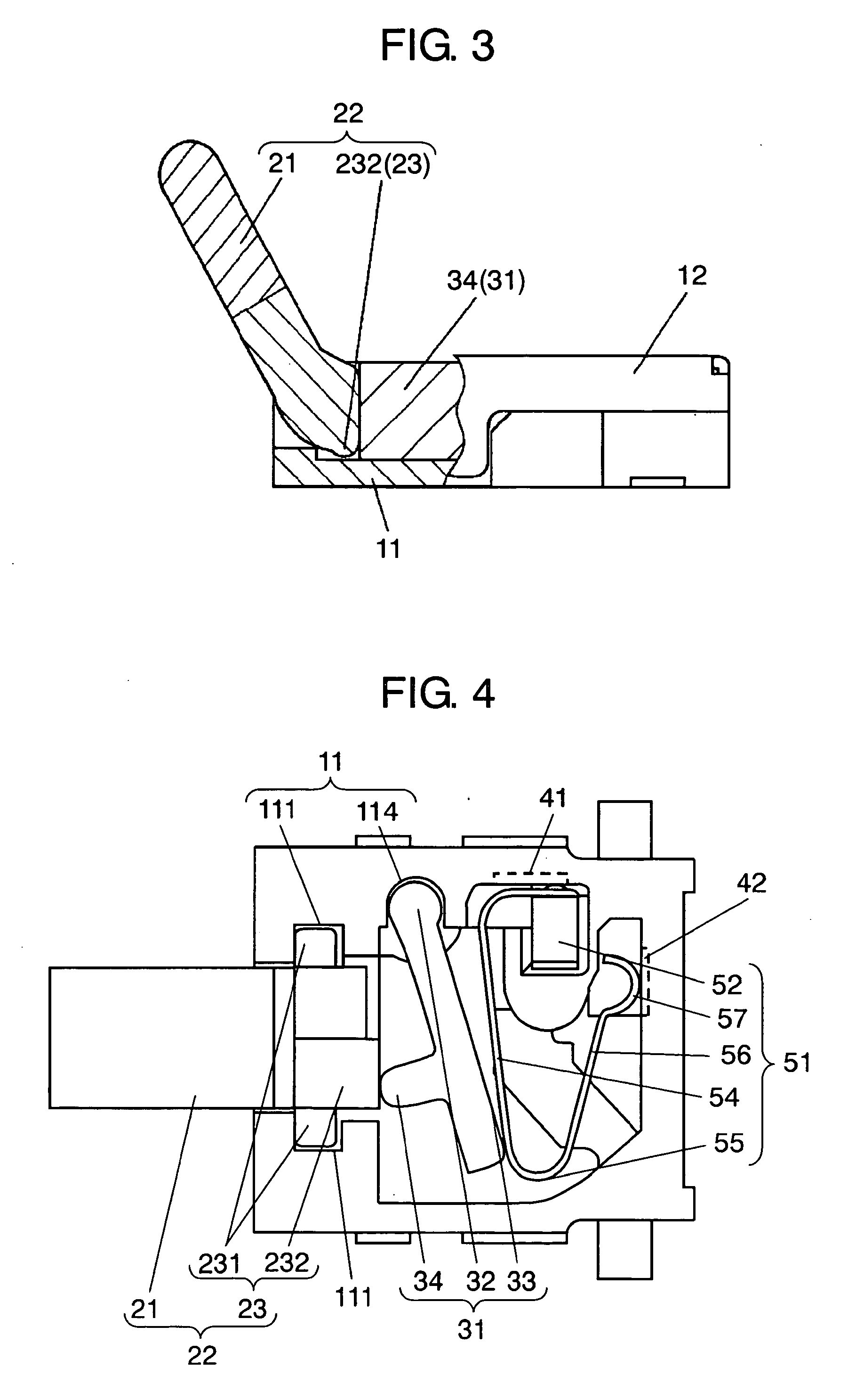
Exemplary embodiments of the present invention are demonstrated hereinafter with reference to the accompanying drawings. FIG. 1 shows a perspective appearance of a switch in accordance with the exemplary embodiment of the present invention. FIG. 2 shows a top view of the switch shown in FIG. 1 without a cover. FIG. 3 shows a lateral sectional view illustrating parts of the switch taken along the line 3-3 of FIG. 2.
In FIG. 1-FIG. 3, box-shaped housing 11, having a recess open upward and made of molded resin, is covered by cover 12 at the top face of its recess. Operating lever 21 shaped like a straight rod projects slantingly upward from the front of housing 11, and lever 21 can be tilted. The side where lever 21 is disposed is referred to as the front of housing 11 and the opposite side is referred to as the rear of housing 11.
Lever 21 works as the operating section of the switch of the present invention, and is made of elastic material such as rubber or elastomer. The root of ...
PUM
 Abstract
Description
Claims
Application Information