Key duplicating machine

a key duplication and key technology, applied in the field of cutting machine tools, can solve the problems of more difficult use and failed duplication of keys, and achieve the effect of improving accuracy and ease of us

Active Publication Date: 2021-01-14
WU KUO SHEN
View PDF0 Cites 0 Cited by
  • Summary
  • Abstract
  • Description
  • Claims
  • Application Information

AI Technical Summary

Benefits of technology

[0009]The main objective of the present invention is to provide a key duplicating machine wherein keys are fixed on a base assembly of the key duplicating machine, and a motor, a guiding element and a cutting element of the key duplicating machine are pivotal and movable for duplicating the keys, which improves accuracy of duplication and ease in use.
[0013]First, the keys are clamped on the first clamp and the second clamp, and both clamps are fixed on the base. Therefore, the reaction force from key cutting can hardly affect the position of the keys, and the precision of key duplication is improved. Moreover, the weight of the cutting module is significantly greater than that of the conventional swing table because the cutting module has a motor, a cutting element and a guiding element. The increased weight reduces the effect of the reaction force from key cutting and stabilizes the position of the guiding element and the cutting element, which further improves the precision of duplication.
[0014]Second, a cutting depth of the cutting element is automatically controlled by the weight of the cutting module pressing against the guiding element and the cutting element, and therefore when duplicating a key, the user only has to control the position where the cutting element cuts by operating the first driving mechanism with one hand. The first driving mechanism moves the guiding element and the cutting element along the first direction or the second direction and completes the duplication. The present invention is easier to use and faster in duplication.

Problems solved by technology

The deviations are gradually accumulated through each duplication process, and finally cause a failed duplicated key.
Second, when duplicating a key, the user needs to control movements of the swing table 92 in two different directions simultaneously, which makes it more difficult to use.

Method used


Image

  • Key duplicating machine
  • Key duplicating machine
  • Key duplicating machine

Examples


Embodiment Construction

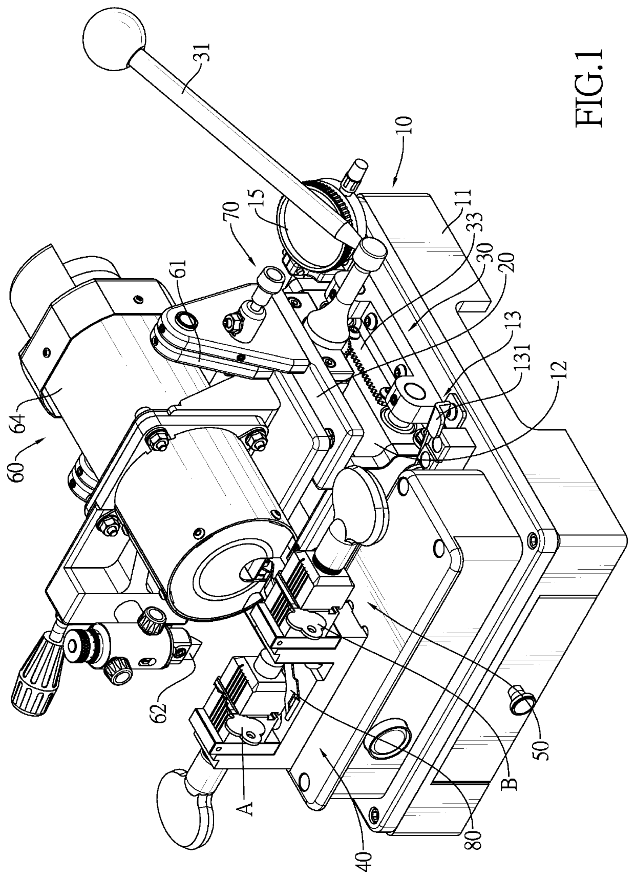
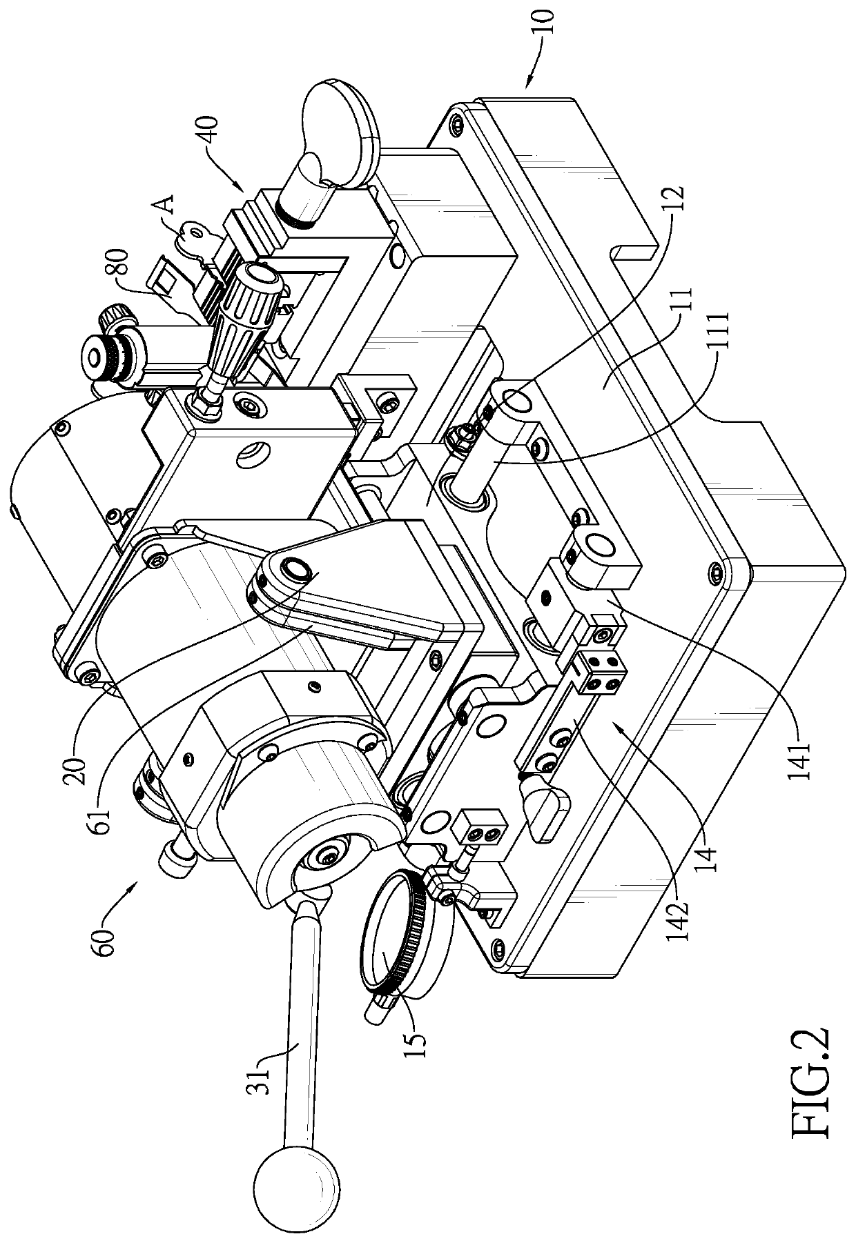
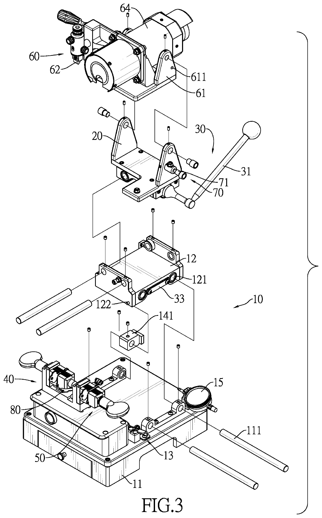
[0033]With reference to FIGS. 1 to 4, a key duplicating machine in accordance with the present invention comprises a base assembly 10, a first sliding table 20, a first driving mechanism 30, a first clamp 40, a second clamp 50 and a cutting module 60. In a preferred embodiment, the present invention further comprises an angular fixing mechanism 70 and a pry bar 80.

[0034]With reference to FIGS. 3 and 4, the base assembly 10 has a base 11, and in a preferred embodiment, the base assembly 10 further has a second sliding table 12, a second driving mechanism 13, a switching mechanism 14 and a distance indicator 15.

[0035]With reference to FIGS. 2, 3, 5 and 6, the base assembly 10 has a first direction D1 and a second direction D2. The first direction D1 and the second direction D2 are opposite to each other. The second sliding table 12 is slidably mounted on the base 11, and is movable in a direction perpendicular to the first direction D1 and the second direction D2. In a preferred embod...


PUM


Abstract

A key duplicating machine is used for duplicating notches of an original key to a key blank. The key duplicating machine includes a base assembly, a first sliding table, a first driving mechanism, a first clamp, a second clamp and a cutting module. The first sliding table is slidably mounted on the base assembly. The first driving mechanism controls a position of the first sliding table. The two clamps are fixed on the base assembly. The original key and key blank are fixed on the two clamps respectively. The cutting module is pivotally mounted on the first sliding table, and has a guiding element, a TO cutting element and a motor. Gravity makes the cutting module rotate, and makes the guiding element and the cutting element press against the keys. The duplicating can be carried out with one hand, which is easier to use and more precise.

Description

BACKGROUND OF THE INVENTION1. Field of the Invention[0001]The present invention relates to a cutting machine tool, especially to a key duplicating machine.2. Description of the Prior Arts[0002]With reference to FIGS. 23 and 24, a conventional key duplicating machine can be used for duplicating shapes of notches on a side of a key. The key duplicating machine comprises a base assembly 91 and a swing table 92. The swing table 92 is pivotally mounted on a pivot shaft 911 of the base assembly 91 and is linearly movable along the pivot shaft 911. A first clamp 921 and a second clamp 922 are fixed on a top of the swing table 92. The base assembly 91 has a cutting element 912, a motor 913 and a guiding element 914. The motor 913 rotates the cutting element 912. A shape of a tip of the guiding element 914 is same as a shape of the edge of the cutting element 912, and a distance between the guiding element 914 and the cutting element 912 is equal to a distance between the first clamp 921 and...

Claims


Application Information

Patent Timeline
Patent Type & Authority Applications(United States)
IPC IPC(8): B23C3/35B23Q3/06
CPCB23C3/35B23Q3/06B23C2235/48B23C2260/48Y10T409/301064
Inventor WU, KUO-SHEN
Owner WU KUO SHEN
Why Eureka
Try Eureka