
Polyaxial bone anchor and method of spinal fixation

a bone anchor and polyaxial technology, applied in the field of bone anchors, can solve the problems of limited degree of angulation, the head of the screw or hook is often out of alignment with one another, and surgeons often encounter considerable difficulty in using this method, and achieve the effect of increasing the angulation of the anchor member

Inactive Publication Date: 2005-04-14
SYNTHES USA
View PDF10 Cites 551 Cited by
  • Summary
  • Abstract
  • Description
  • Claims
  • Application Information

AI Technical Summary

Problems solved by technology

Surgeons have often encountered considerable difficulty when using this method, due to trouble aligning the spinal rod(s) with the U-shaped channels in the heads of the screws or hooks.
For example, the heads of the screws or hooks are often out of alignment with one other due to the curvature of the spine or the size and shape of each vertebrae.
One limitation with these devices, however, is that the degree of angulation can be limited due to contact between the shank of the screw or hook, and the lower bounding edge of the body.
This can be problematic in certain spinal applications where increased angulation is required, for example, in treatment of the cervical region of the spine.

Method used


Image

  • Polyaxial bone anchor and method of spinal fixation
  • Polyaxial bone anchor and method of spinal fixation
  • Polyaxial bone anchor and method of spinal fixation

Examples


Embodiment Construction

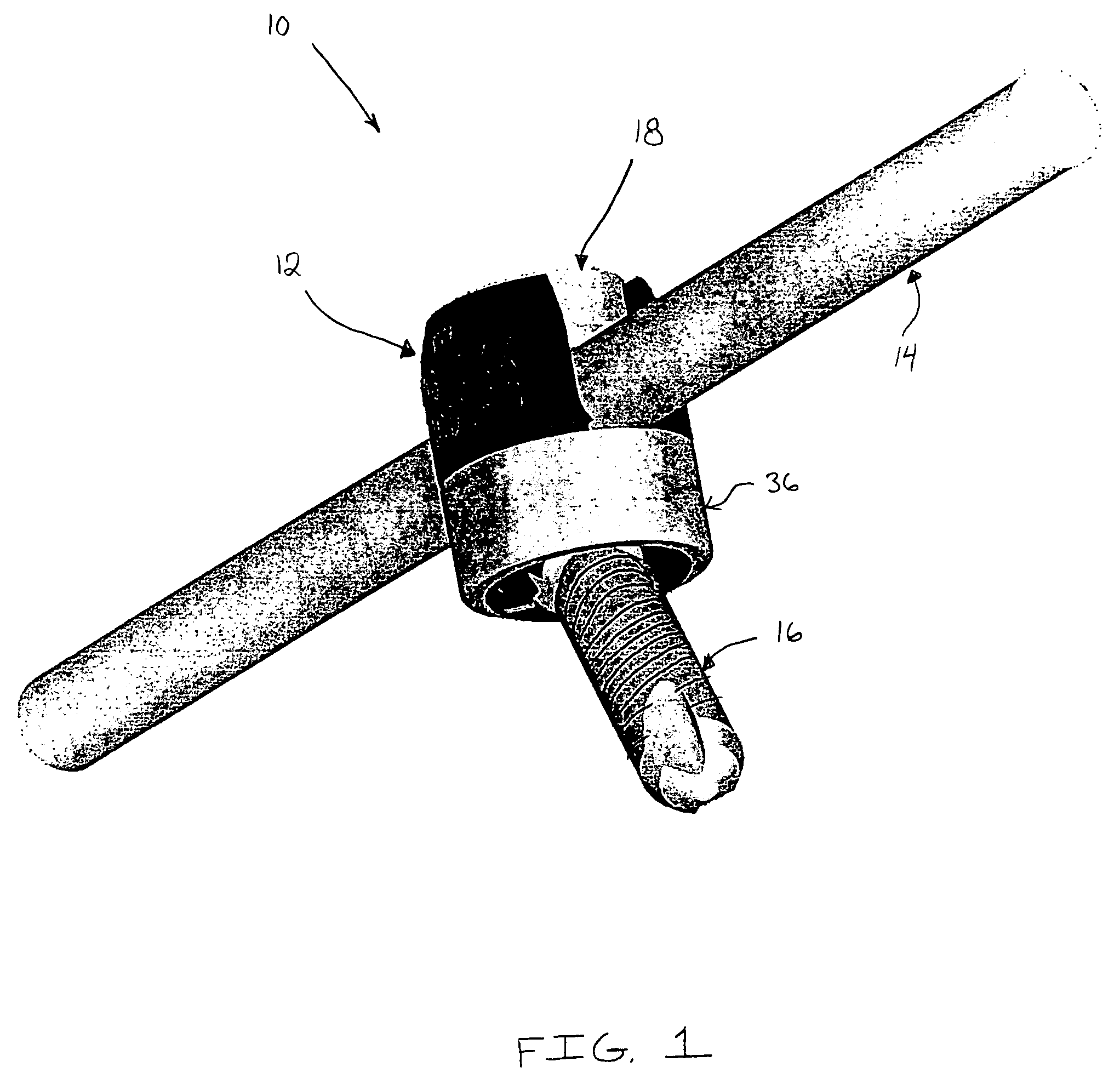
[0033] Referring to FIG. 1, a first illustrative embodiment of a polyaxial bone anchor according to the present invention is shown. Polyaxial bone anchor 10 generally includes a body 12 having a channel for receiving a spinal rod 14 or other device, an anchor member 16 attached to body 12 such that it can polyaxially rotate with respect to body 12, and a fastener 18 for securing the spinal rod 14 to body 12. Fastener 18 may also fix the angular position of anchor member 16 with respect to body 12. One or more polyaxial bone anchors 10 may be attached to the vertebrae via anchor member 16 (shown as a bone screw) and positioned along the spinal rod 14, or other device, to correctly align the spine or treat other spinal disorders.

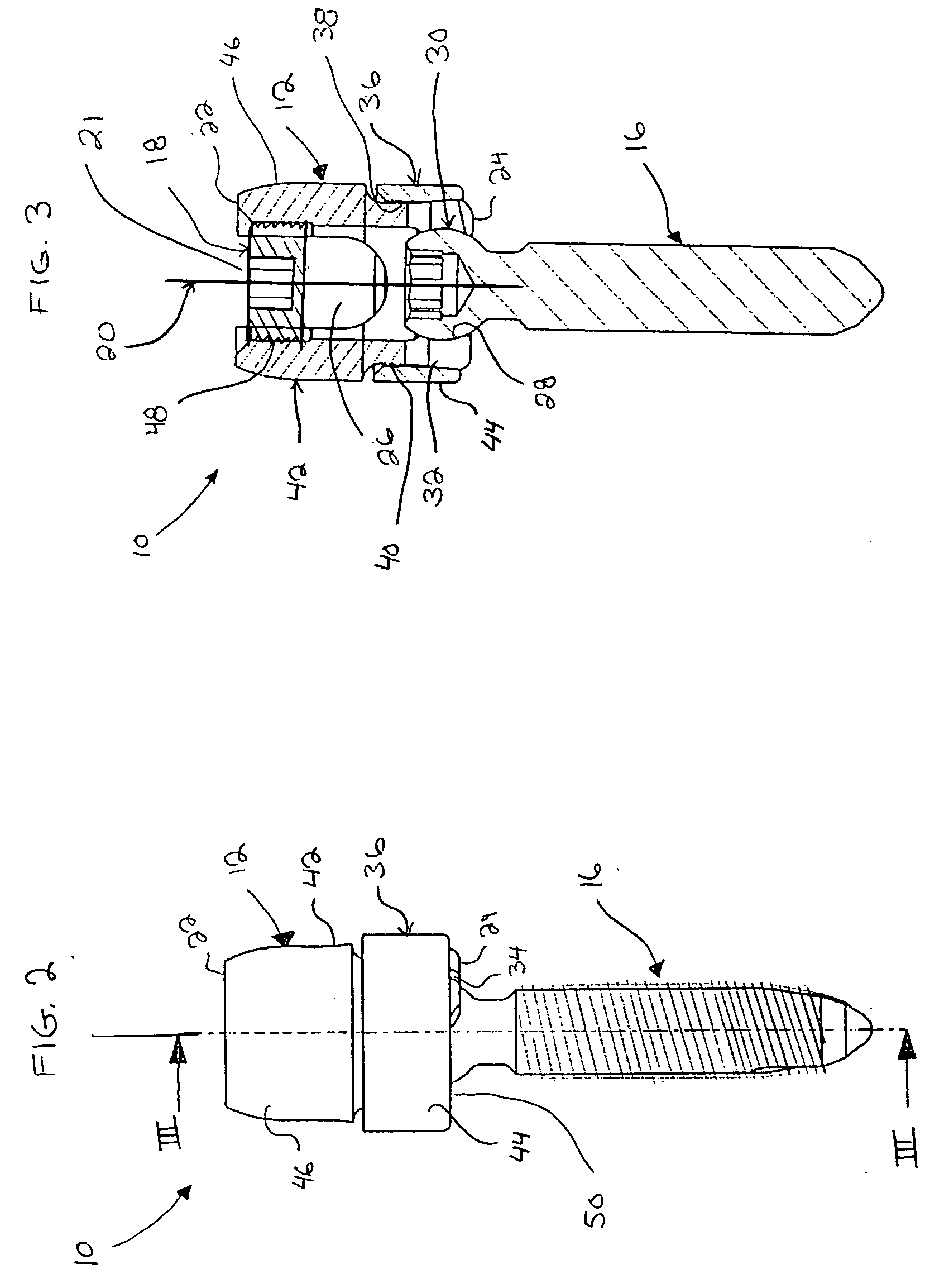
[0034] Referring to FIGS. 2 and 3, side and cross-sectional views of polyaxial bone anchor 10 are shown, respectively. As shown, body 12 may comprise a generally cylindrical member defining a first axis 20, an upper bounding edge 22 and a lower bounding edge ...


PUM


Abstract

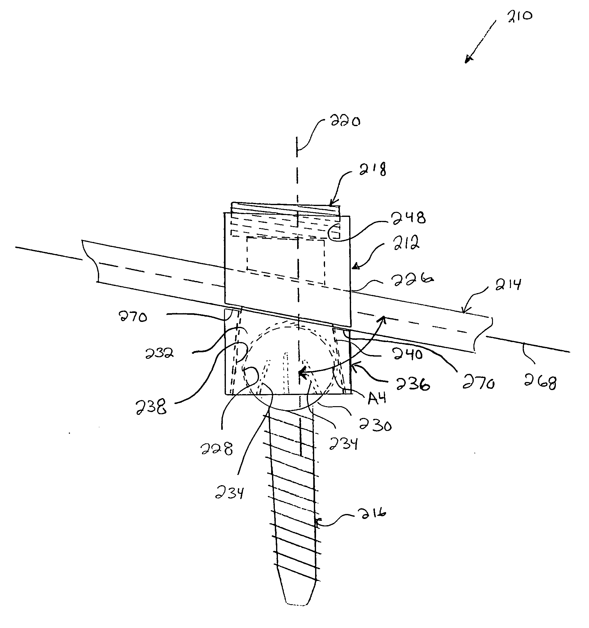
The present invention is directed to a polyaxial bone anchor for attaching a rod to a bone comprising an anchor member for attachment to the bone, a body member having a U-shaped channel for receiving the rod and a compressible recess for receiving a head of the anchor member such that the anchor member can initially polyaxially angulate with respect to the body member, a collar slidably disposed about the body member and capable of compressing the recess around the head, and a fastener capable of pressing the rod against the collar. The body member may define a first axis, an upper bounding edge, and a lower bounding edge, and the lower bounding edge may include a countersunk region to permit increased angulation of the anchor member with respect to the first axis when the anchor member is oriented toward the countersunk region. Other structures for providing increased angulation of the anchor member are disclosed as well. Further, the present invention is directed to methods of fixation of the cervical region of the spine.

Description

TECHNICAL FIELD OF THE INVENTION [0001] The present invention relates generally to bone fixation devices and related methods of fixation. More specifically, the present invention relates to polyaxial bone anchors, such as screws and hooks for spinal fixation, and related methods of spinal fixation. BACKGROUND OF THE INVENTION [0002] There are many methods of treating spinal disorders known in the art. One known method involves anchoring a screw or a hook to the vertebrae, and fixing the screws or hooks along a spinal rod to position or immobilize the vertebrae with respect to one another. The screws or hooks commonly have heads with U-shaped channels that the spinal rod is inserted into and subsequently clamped into by a set screw or other fastener mechanism. This method may commonly involve multiple screws or hooks, as well as multiple spinal rods. With this method, the spinal rod(s) may be shaped to maintain the vertebrae in such an orientation as to correct the spinal disorder at...

Claims


Application Information

Patent Timeline
Patent Type & Authority Applications(United States)
IPC IPC(8): A61B17/70
CPCA61B17/7032A61B17/7038A61B17/7037A61B17/70A61B17/72
Inventor KEYER, THOMAS R.BERGER, ROGERWALTHER, MARTIN
Owner SYNTHES USA
Learn More