Vehicle motion control apparatus

a technology of motion control and steering control device, which is applied in the direction of underwater vessels, non-deflectable wheel steering, braking components, etc., to achieve the effect of minimizing the disadvantages of steering control device inoperativeness

Active Publication Date: 2005-04-21
JTEKT CORP +1
View PDF6 Cites 10 Cited by
  • Summary
  • Abstract
  • Description
  • Claims
  • Application Information

AI Technical Summary

Benefits of technology

[0016] Each apparatus may further include a steering monitor for monitoring an operating state of the steering control device. Then, the motion control device may be adapted to modify the second threshold value to be larger in margin

Problems solved by technology

And, it is described that a future issue to be considered is a tota

Method used


Image

  • Vehicle motion control apparatus
  • Vehicle motion control apparatus
  • Vehicle motion control apparatus

Examples


Embodiment Construction

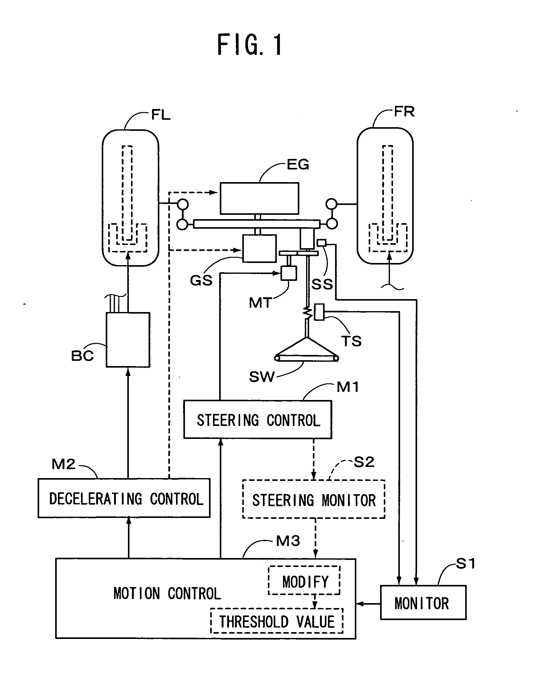
[0028] Referring to FIG. 1, there is schematically illustrated a block diagram of a vehicle motion control apparatus according to the present invention. The apparatus includes a steering control device Ml for controlling a relationship between a steering angle and a tire angle to be varied, with respect to front wheels FL and FR, and a decelerating control device M2 for controlling a vehicle speed to be decreased. The decelerating control according to the latter device means such a control as decreasing the vehicle speed irrespective of operation of a vehicle driver. An example of the decelerating control device M2 is a hydraulic braking pressure control device BC. As indicated by broken lines in FIG. 1, however, the vehicle speed may be decreased by controlling a throttle opening of an engine EG, or controlling a shift control device GS to shift down a gear ratio thereof.

[0029] Then, a parameter indicative of lateral margin for a tire (FL or FR) is monitored by a monitor S1, and t...


PUM


Abstract

A vehicle motion control apparatus is provided for performing a vehicle stability control on the basis of a parameter indicative of lateral margin for a tire on a road. The apparatus includes a steering control device for controlling a relationship between a steering angle and a tire angle to be varied, and a decelerating control device for controlling a vehicle speed to be decreased. The parameter indicative of lateral margin for the tire is monitored, and the steering control device and the decelerating control device are controlled on the basis of the monitored parameter. The steering control device is controlled to decrease the tire angle relative to the steering angle, when the parameter is decreased from a value of relatively large lateral margin to a value of relatively small lateral margin, which is smaller than a first threshold value, and the decelerating control device is controlled to decrease the vehicle speed in addition to the steering control by the steering control device, when the parameter is further decreased to a value of lateral margin smaller than a second threshold value, which is smaller than the first threshold value.

Description

[0001] This application claims priority under 35 U.S.C. Sec. 119 to No. 2003-311932 filed in Japan on Sep. 3, 2003, the entire content of which is herein incorporated by reference. BACKGROUND OF THE INVENTION [0002] 1. Field of the Invention [0003] The present invention relates to a vehicle motion control apparatus, particularly relates to an apparatus for performing a vehicle stability control in response to state of a tire on a road. [0004] 2. Description of the Related Arts [0005] In general, when a vehicle is moving with a motion in a lateral direction or yawing motion, a rotating plane of a wheel is not directed to a moving direction of a vehicle on a road, so that a so-called lateral slip is caused. As a parameter or factor indicative of that state of the wheel, a slip angle, or wheel slip angle is employed. According to a book entitled “Vehicle Dynamics and Control” written by Mr. Masato Abe in Japanese, and published by Sankaido Co., Ltd., on May 31, 1994, it is defined that...

Claims


Application Information

Patent Timeline
IPC IPC(8): B60T8/1755B60W10/00B60W10/04B60W10/06B60W10/10B60W10/18B60W10/188B60W10/20B62D5/04B62D6/00B62D103/00B62D113/00B62D119/00B62D137/00
CPCB60T8/1755B62D6/006B60T2260/02
Inventor AIZAWA, HIROAKINIINO, HIROAKIMOMIYAMA, MINEKAZUKATO, HIROAKIONO, EIICHIMURAGISHI, YUJIYASUI, YOSHIYUKI
Owner JTEKT CORP
Why Eureka
Try Eureka