Display device and drive method thereof

a display device and drive method technology, applied in static indicating devices, non-linear optics, instruments, etc., can solve the problem of difficult to maintain a sufficient sampling period of time for sequential sampling of video signals input by one system with respect to all pixels within a limited horizontal effective period, so as to prevent the occurrence of vertical streaks or other image defects reliably, improve image quality

Inactive Publication Date: 2006-10-19
SONY CORP
View PDF4 Cites 13 Cited by
  • Summary
  • Abstract
  • Description
  • Claims
  • Application Information

AI Technical Summary

Benefits of technology

[0014] According to the present invention, the horizontal start pulse has a pulse width that includes a plurality of pulse widths in the first clock pulses, and a margin in the phase relationship between the second clock pulse and the transfer pulse is large, so that, even if delay or waveform rounding occurs in the second clock pulse, the sampling pulse with a constant pulse width equal to that of the second clock pulse can be generated. As a result, the occurrence of vertical streaks or other image defects can be prevented reliably, thus improving image quality.

Problems solved by technology

For an active matrix display apparatus that uses the dot sequential driving mode, when the number of pixels in a horizontal direction, in particular, is increased as the display apparatus realize a higher resolution, it becomes difficult to maintain a sufficient sampling period of time for sequentially sampling video signals input by one system with respect to all pixels within a limited horizontal effective period.
However, if the simultaneous sampling number, m, is increased, a problem to be solved arises in which the waveform of a sampling pulse for driving a horizontal switch for sampling a video signal and writing it into a signal line is more rounded, which is caused by resistance and capacitive load in transients.
Such delay in sampling pulses and waveform rounding thereof is a factor that causes ghosts.

Method used


Image

  • Display device and drive method thereof
  • Display device and drive method thereof
  • Display device and drive method thereof

Examples


example

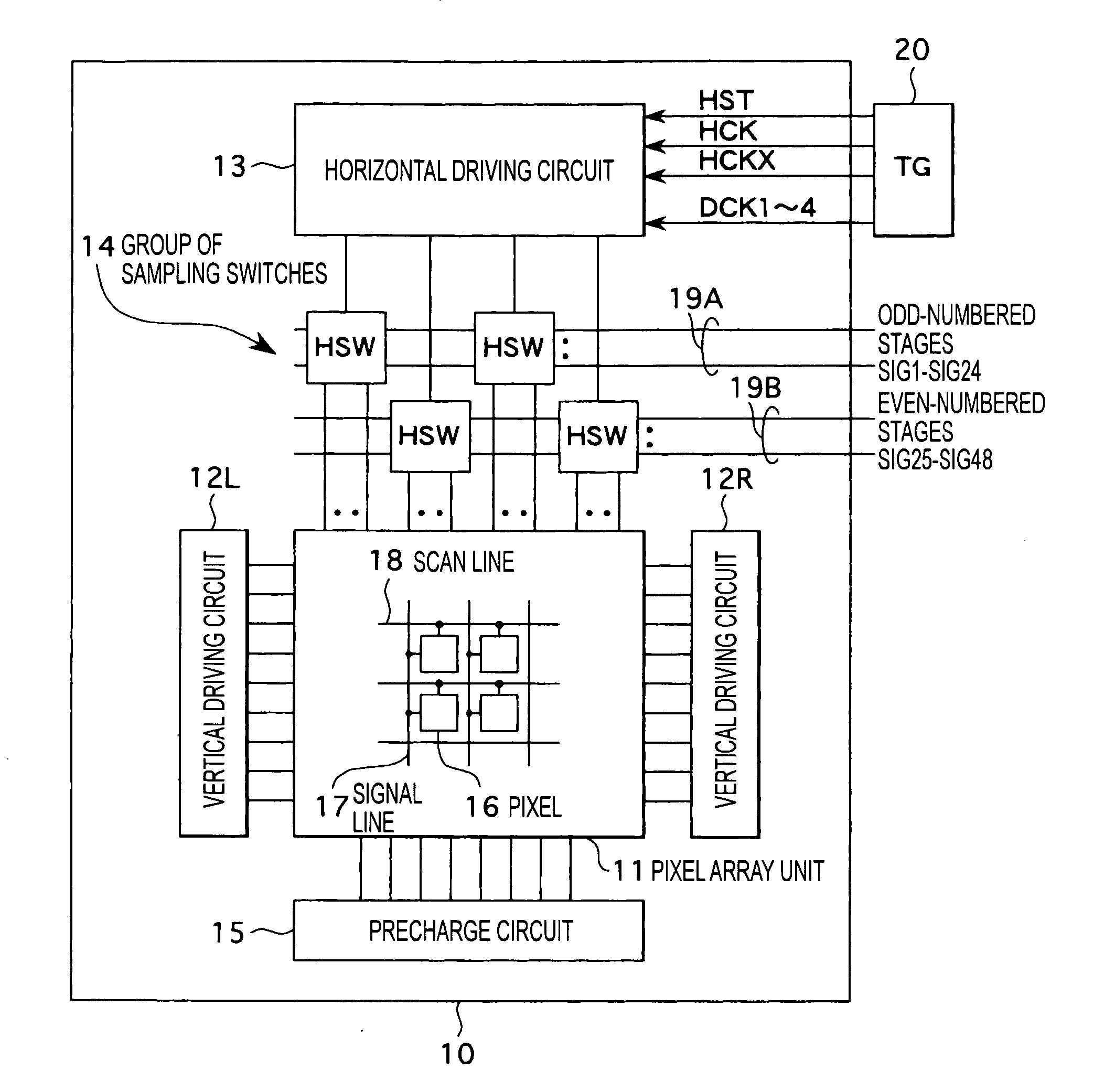
[0056]FIG. 9 is a circuit diagram showing a concrete example of the display apparatus according to the embodiment. In FIG. 9, components similar to those in FIG. 1 have the same reference numerals.

[0057] The display apparatus according to this example is an active matrix LCD apparatus that uses the dot sequential driving mode and that uses LCD cells as display elements (electrooptic elements) in the pixels 16. Here, for the sake of simplification of the figure, a 4 by 4 matrix of pixels is shown as an instance. For an LCD apparatus, the display panel 10 shown in FIG. 1 is a LCD panel in which two transparent substrates that face each other with a predetermined gap therebetween filled with a liquid crystal substance are integrally formed. The two transparent substrates are composed of, for example, a first glass substrate that is a TFT substrate in which TFTs serving as pixel transistors are arranged and a second glass substrate that is an opposing substrate arranged so as to face t...


PUM

PropertyMeasurementUnit
widthaaaaaaaaaa
pulse widthaaaaaaaaaa
resistanceaaaaaaaaaa

Abstract

A display apparatus and a method for driving the display apparatus that are capable of suppressing image quality degradation resulting from delay in sampling pulses or from waveform rounding thereof and image quality degradation caused by coupling between the signal line and the common line and that between the signal line and the scan line even when the simultaneous sampling number is increased. The start pulse HST has a pulse width that includes a plurality of pulse widths of the clock pulses HCK and HCKX, for example, two pulse widths. The clock pulses DCK have four phases. Large margins α1 and α2 in the phase relationship between each of the clock pulses DCK1 to DCK4 and each of transfer pulses used for extracting the clock pulses DCK1 to DCK4 are assured. As a result, even if delay or waveform rounding occurs in the clock pulses DCK1 to DCK4, sampling pulses SP1 to SP6 with a constant pulse width equal to that of each of the clock pulses DCK1 to DCK4 can be generated without being affected by the delay or waveform rounding.

Description

TECHNICAL FIELD [0001] The present invention relates to a display apparatus and a method for driving the display apparatus. In particular, the present invention relates to an active matrix display apparatus that uses a dot sequential driving mode and a method for driving the active matrix display apparatus. BACKGROUND ART [0002] In an active matrix apparatus that includes a pixel array unit in which pixels including electrooptic elements are arranged in a matrix with a large number of rows and columns and a scan line is wired for each row and a signal line is wired for each column with respect to the pixel arrangement, a vertical driving circuit configured to select each pixel in the pixel array unit on a row-by-row basis, and a horizontal driving circuit configured to write a video signal into each pixel in a row selected by the vertical driving circuit, a dot sequential driving mode is a method that sequentially samples, e.g., analog video signals that are serially input over one ...

Claims


Application Information

Patent Timeline
Patent Type & Authority Applications(United States)
IPC IPC(8): G09G3/36G09G3/20G02F1/133
CPCG09G3/3688G09G2320/0209G09G2310/0297G09G3/36G09G3/20G02F1/133
Inventor KOBAYASHI, HIROSHIHARANO, TAMAKI
Owner SONY CORP
Why Eureka
Try Eureka