Whirlwind dusting machine

A dust collector, cyclone technology

Inactive Publication Date: 2009-11-25
TWINBIRD CORP
View PDF7 Cites 9 Cited by
  • Summary
  • Abstract
  • Description
  • Claims
  • Application Information

AI Technical Summary

Problems solved by technology

[0005] However, in such a cyclone type dust collector, since the above-mentioned vortex generating member is difficult to grasp, when the above-mentioned vortex generating member is removed in order to discard the accumulated dust, there are the above-mentioned vortex generating members with fine dust attached to the surface. Possibility of contamination caused by falling onto the surface to be cleaned
In addition, in the case of a structure in which the

Method used


Image

  • Whirlwind dusting machine
  • Whirlwind dusting machine
  • Whirlwind dusting machine

Examples


Embodiment Construction

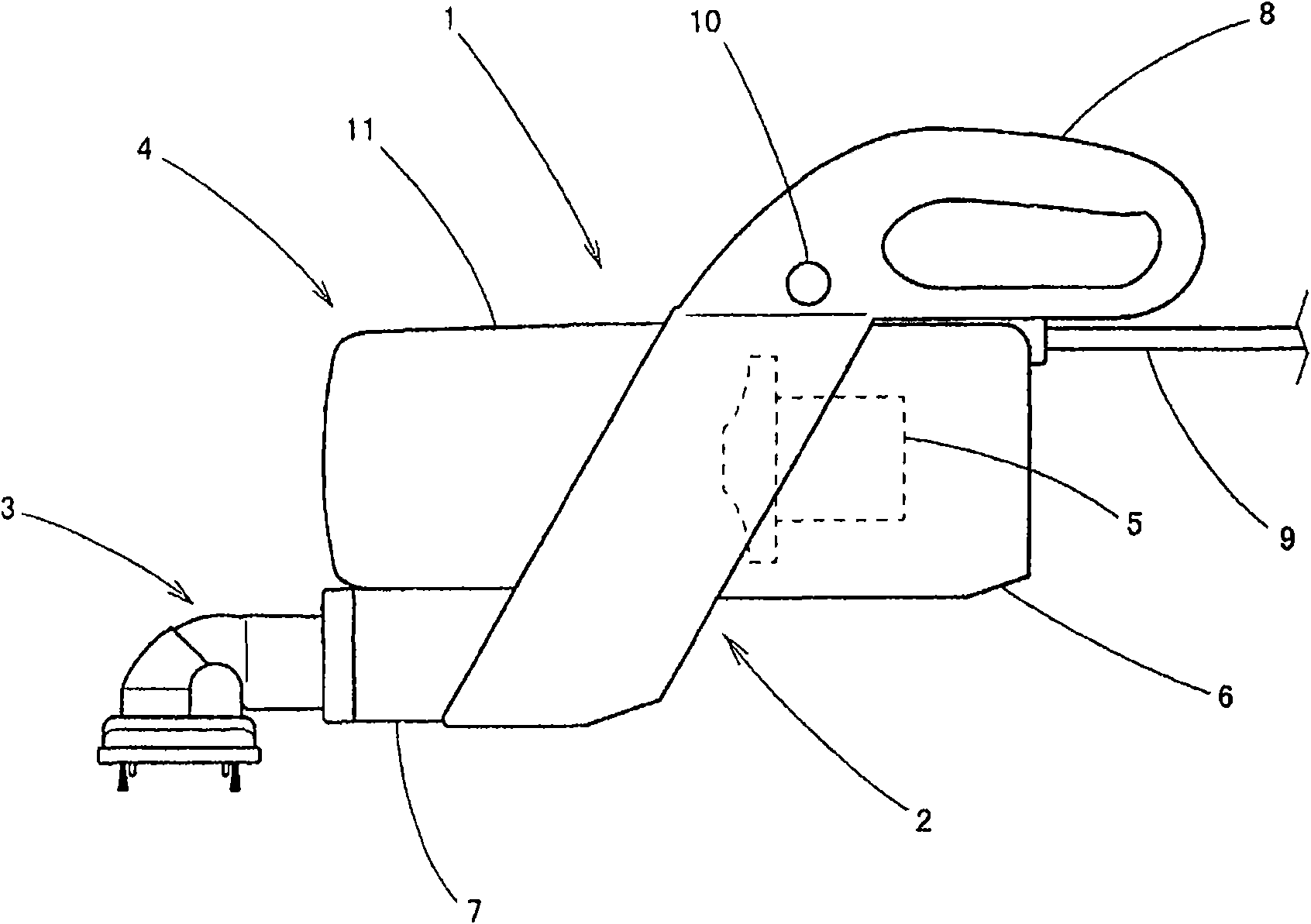
[0037] Below, according to Figure 1 to Figure 7 , to describe the embodiment of the present invention. 1 is a portable cyclone dust collector. This cyclone dust collector 1 is constituted by having a dust collector body 2 , a nozzle 3 detachably attached to the dust collector body 2 , and a dust collecting member 4 detachably attached to the dust collector body 2 .

[0038] The dust collector body 2 is constituted by having a main body 6 in which an electric blower 5 is built, a connecting portion 7 having a suction path not shown inside, a grip 8 and a power cord 9 . Moreover, the operation part 10 for attaching and detaching the said dust collection member 4, and the switch operation part which are not shown in figure are provided in the said grip part 8. As shown in FIG. Further, the nozzle 3 is detachably attached to one end of the suction path of the connection portion 7 .

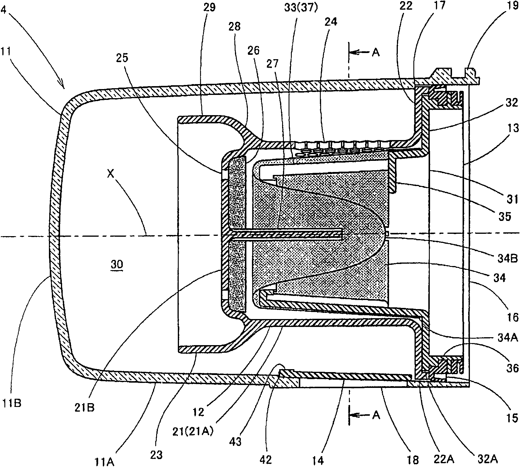
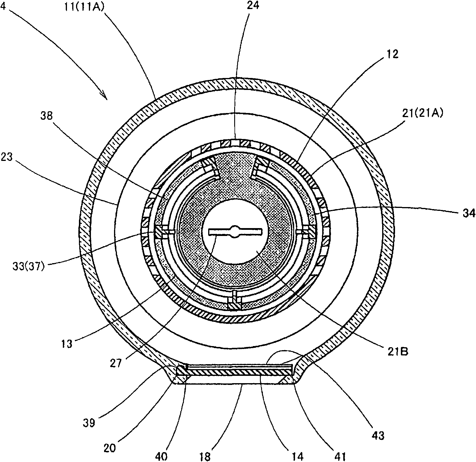
[0039] The dust collecting member 4 is constituted by having a dust collecting container 11 , ...


PUM


Abstract

The invention provides a whirlwind dusting machine capable of easily demounting a tubular body to easily abandon dust. The tubular body (12) with a dust collection container (11) is installed with free dismounting relative to the dust collection container (11) and is provided with small holes (24), (25) playing the role of a primary filter and a secondary filter body (13) is installed at the downriver side of the tubular body with free dismounting and is provided with a baggy secondary filter (34) so that a dust collection member (4) is installed with free dismounting relative to the dusting machine body (2) internally provided with an electronic ventilating blower (5); moreover, a protuberance (27) in projecting manner extended to the side of the second filter (34) is installed at the central part of the tubular body (12), so the tubular body (12) can be held easily by grasping the protuberance (27) when the tubular body (12) is dismounted relative to the dust collection container (11); thereof, the possibility that the protuberance (27) drops off can be reduced.

Description

technical field [0001] The present invention relates to a cyclone dust collector, in particular to a cyclone dust collector which is easy to care for dust collecting components. Background technique [0002] In the past, as this kind of cyclone dust collector, there is a dust collector body with a built-in blower, a dust collection container detachably attached to the dust collector body, and a dust collection container detachably installed in the opening of the dust collection container. A vortex generating member with a short cylindrical or truncated short cone-shaped base (equivalent to the cylindrical body of the present invention), and a filter member (equivalent to the second embodiment of the present invention) detachably installed on the downstream side of the vortex generating member. A cyclone dust collector is known (for example, refer to Patent Document 1). And, by operating the above-mentioned blower, the dust is centrifugally separated from the air flow in the...

Claims


Application Information

Patent Timeline
IPC IPC(8): A47L9/10
Inventor 松尾和则金安浩
Owner TWINBIRD CORP
Why Eureka
Try Eureka