Method and apparatus for detecting foreign body on object surface, and optical disk apparatus

a technology of optical disk and object surface, which is applied in the direction of digital signal error detection/correction, instruments, recording signal processing, etc., can solve the problems of affecting the accuracy of optical disk apparatus having a high information recording density, affecting the accuracy of optical disk apparatus, etc., to achieve the effect of high accuracy, large variation margin, and high accuracy

Inactive Publication Date: 2007-07-03
PANASONIC CORP
View PDF11 Cites 11 Cited by
  • Summary
  • Abstract
  • Description
  • Claims
  • Application Information

AI Technical Summary

Benefits of technology

[0011]Therefore, the present invention has been made to solve the conventional problems. Accordingly, an object of the present invention is to provide a method and apparatus which are capable of detecting a foreign body with a reflectance which is slightly different from a reflectance of the medium or a transparent foreign body at high accuracy, and providing a large margin for a variation of a photodetector. It is another object of the invention to provide a foreign body detection apparatus which is capable of detecting a foreign body at a high accuracy and a low cost even in an ordinary measurement environment. It is still another object to provide an optical disk apparatus and a system equipped with the optical disk apparatus which can achieve recording / reproducing high-density information and provide high reliability against a foreign body.(Method of Solving the Problems)

Problems solved by technology

However, with the advance of miniaturization of these devices, important technical problems have arisen for realizing integration higher than conventional integration by detecting and removing a foreign body such as a stain, dust, an oil film, or a scratch.
In manufacturing or use of a product, a foreign body adhering to the device causes a decrease in manufacturing yield or product performance.
More specifically, in the case where recording marks are reduced in size by using a short-wavelength light source such as a blue laser to increase a recording bit density, when even a foreign body which does not cause any problem on a compact disk adheres to an optical path of a light beam, the following problem arises.
Therefore, the optical disk apparatus having a high information recording density cannot be easily put into practical use.
Thus, recording marks having high reliability and a high information recording density cannot be easily formed at high accuracy.
When a light beam is irradiated on the recording layer and the track layer of a phase change recording medium or a pigmentary change recording medium to read recording marks, the light beam is similarly affected by light shielding, refraction, reflection, or the like depending on the optical characteristics of a foreign body adhering to the surface of the optical disk, and thus, the recording marks and tracks cannot be correctly read.
Therefore, recording marks having a high information recording density cannot be easily read at high accuracy.
However, an optical disk apparatus with an increased capacity by increasing an information recording density has poor recording / reproducing reliability against a foreign body.
Thus, when the optical disk apparatus is mounted on an apparatus or a system such as a computer apparatus, a computer system, a computer network system, a vehicle such as an automobile, a train, a ship, or an airplane, and an image complex apparatus such as an MFP (Multi-Function Product) which require recording / reproducing reliability, the reliabilities of the apparatuses and the systems are disadvantageously deteriorated.

Method used


Image

  • Method and apparatus for detecting foreign body on object surface, and optical disk apparatus
  • Method and apparatus for detecting foreign body on object surface, and optical disk apparatus
  • Method and apparatus for detecting foreign body on object surface, and optical disk apparatus

Examples


first embodiment

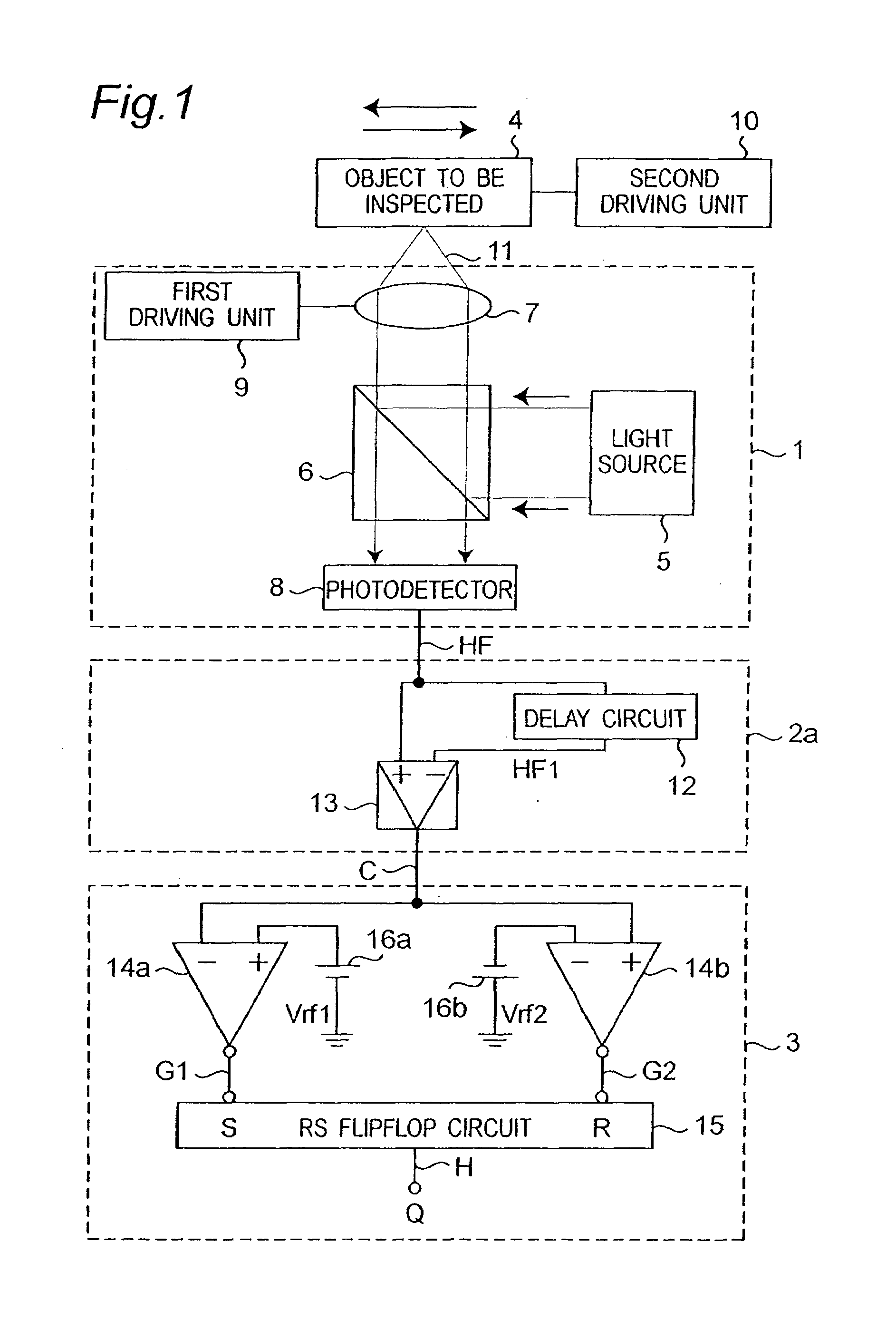
[0073]FIG. 1 is a block diagram showing the first configuration of a foreign body detection apparatus according to the present invention. The foreign body detection apparatus includes a photodetection signal generation unit 1, a foreign body detection signal generation unit 2a, a foreign body discrimination signal generation unit 3, and a second driving unit 10 for horizontally moving an object 4 to be inspected.

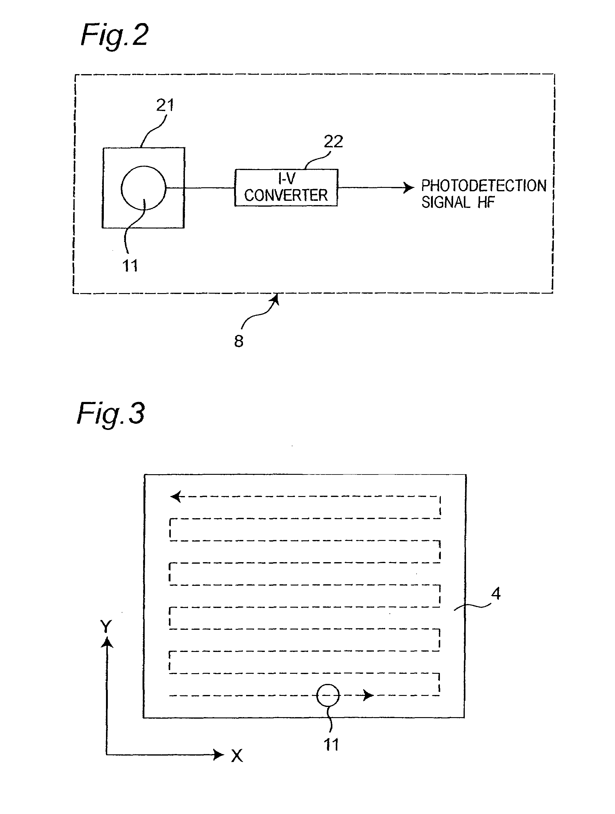
[0074]The photodetection signal generation unit 1 is a unit which detects a beam reflected by the surface of the object 4 to be inspected to generate a photodetection signal HF, and includes a light source 5, a beam splitter 6, a convergence means 7 such as an object lens, a photodetector 8, and a first driving unit 9 for moving a focal point of the convergence means 7.

[0075]As the light source 5, any well-known light source such as an incandescent lamp, a halogen lamp, a semiconductor laser, or a gas laser can be applied. Of these light sources, a light source such as a las...

second embodiment

[0097]FIG. 9 is a block diagram showing the second configuration of a foreign body detection apparatus according to the present invention. The detection apparatus includes a photodetection signal generation unit 1, a foreign body detection signal generation unit 2b, a foreign body discrimination signal generation unit 3, and a second driving unit 10 for horizontally moving the object 4 to be inspected. The configurations and operations of the photodetection signal generation unit 1 and the foreign body discrimination signal generation unit 3 are the same as those described in FIG. 1.

[0098]The foreign body detection signal generation unit 2b includes a first delay circuit 32 and a second delay circuit 33 for delaying a photodetection signal HF output from the photodetector 8, and a subtractor 13. The subtractor 13 subtracts a delay signal HF3 output from the second delay circuit 33 from a delay signal HF2 output from the first delay circuit 32 to generate a difference signal D.

[0099]...

third embodiment

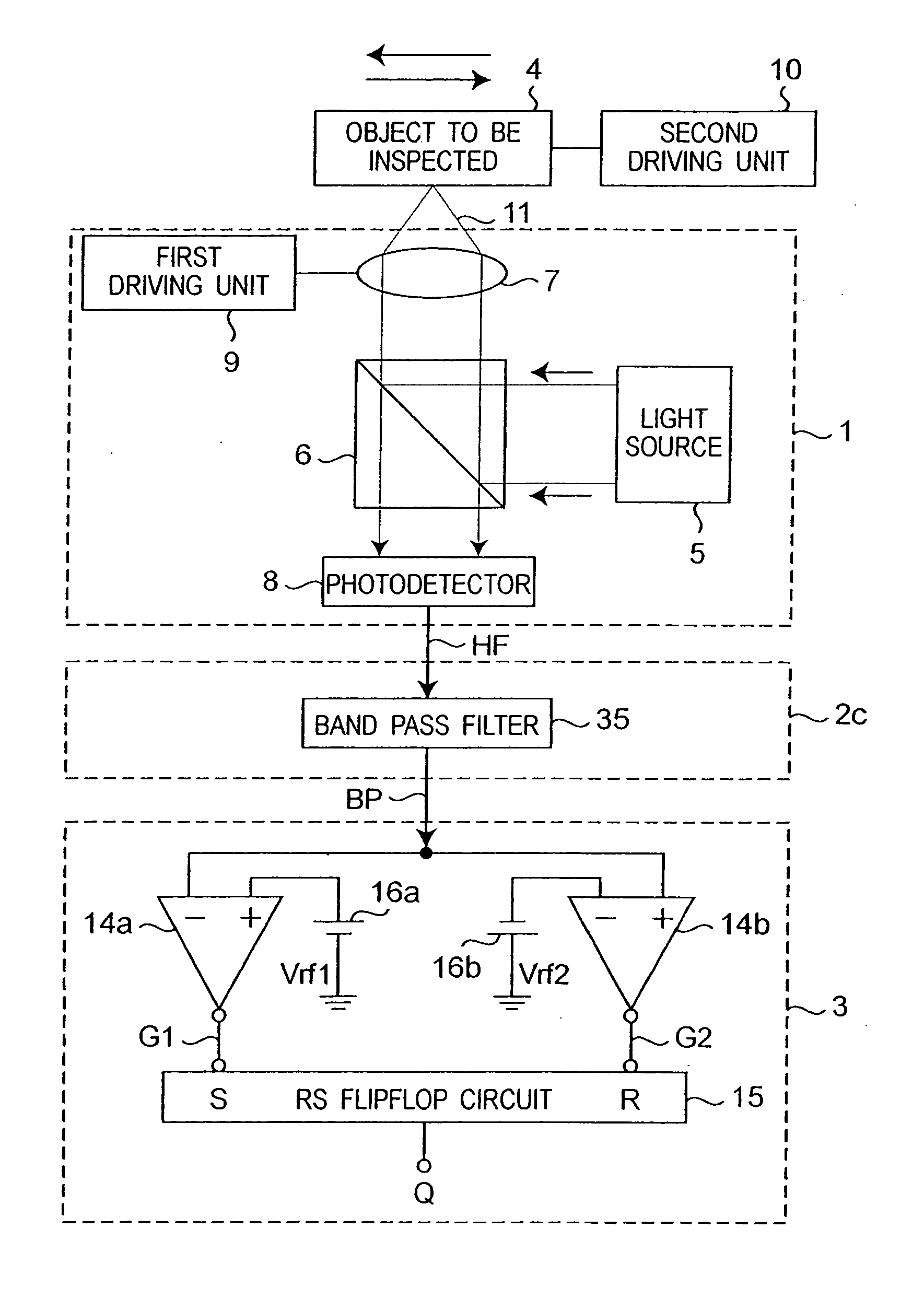
[0107]FIG. 11 is a block diagram showing the third configuration of the foreign body detection apparatus according to the present invention. The foreign body detection apparatus includes a photodetection signal generation unit 1, a foreign body detection signal generation unit 2c, and a foreign body discrimination signal generation unit 3. The configurations and operations of the photodetection signal generation unit1 and the foreign body discrimination signal generation unit 3 are the same as those shown in FIG. 1.

[0108]The foreign body detection signal generation unit 2c includes a band-pass filter 35 which removes unnecessary band components of a photodetection signal HF output from the photodetector 8 to generate a band-pass signal. The band-pass filter 35 has a band-pass characteristic to pass only a predetermined frequency band ft as shown in FIG. 12.

[0109]The foreign body discrimination signal generation unit 3 is different from that of the first embodiment in that a band-pas...


PUM

PropertyMeasurementUnit
frequencyaaaaaaaaaa
velocityaaaaaaaaaa
thicknessaaaaaaaaaa

Abstract

In an foreign body detection apparatus, an optical signal detection unit irradiates a light spot onto a surface of an object to be inspected while scanning the surface by employing the light spot in a predetermined direction, and receives a reflected beam from the surface of the inspected object to generate a photodetection signal corresponding to the light intensity of the reflected beam. A foreign body detection unit generates a foreign body detection signal appearing with respect to a leader and a trailer in the scanning direction of a foreign body adhering to the inspected object from the photodetection signal. The foreign body detection signal is obtained, for example, as a difference signal between the photodetection signal and a delayed photodetection signal with a predetermined delay time. A foreign body discrimination unit generates a foreign body discriminating signal indicating a region in which the foreign body is present from the foreign body detection signal.

Description

TECHNICAL FIELD[0001]The present invention relates to a method and apparatus for detecting a foreign body such as a stain, dust, an oil film, a fingerprint, a scratch, or a defect adhering to or made on a surface of an object. In addition, the present invention relates to an optical disk apparatus which detects a foreign body on an optical disk surface by using the foreign body detection apparatus, and to various systems equipped with the optical disk apparatus.BACKGROUND ART[0002]In recent years, demands for an increase in information recording density on an optical disk recording / reproducing device (to be referred to as an “optical disk apparatus” unless otherwise noted hereinafter) using a phase change recording medium, a pigmentary change recording medium, a magneto-optical recording medium, an optical recording medium (to be referred to as an “optical disk” unless otherwise noted hereinafter) such as a read-only medium on which data is recorded in advance with concavo-convex or...

Claims


Application Information

Patent Timeline
Patent Type & Authority Patents(United States)
IPC IPC(8): G01N21/88G01N21/90G01N21/94G01N21/95G11B7/0037G11B19/04
CPCG01N21/94G01N21/9506G11B7/00375G11B19/04G01N2201/1045
Inventor GOTOH, YASUHIRONISHIWAKI, SEIJIKOMMA, YOSHIAKI
Owner PANASONIC CORP
Why Eureka
Try Eureka