
Injection apparatus and method

a technology of injection apparatus and injection chamber, which is applied in the field of injection apparatus or micro-injection apparatus, can solve the problems of difficult insertion, manual injection, and inconvenient medical application of biological and chemical approaches, and achieve the effect of ensuring the margin

Inactive Publication Date: 2007-06-28
FUJITSU LTD
View PDF15 Cites 11 Cited by
  • Summary
  • Abstract
  • Description
  • Claims
  • Application Information

AI Technical Summary

Benefits of technology

[0009] The present invention is directed to an injection apparatus and method, which can precisely inject a material into a specific region in a minute object with a high throughput in the injection approach.
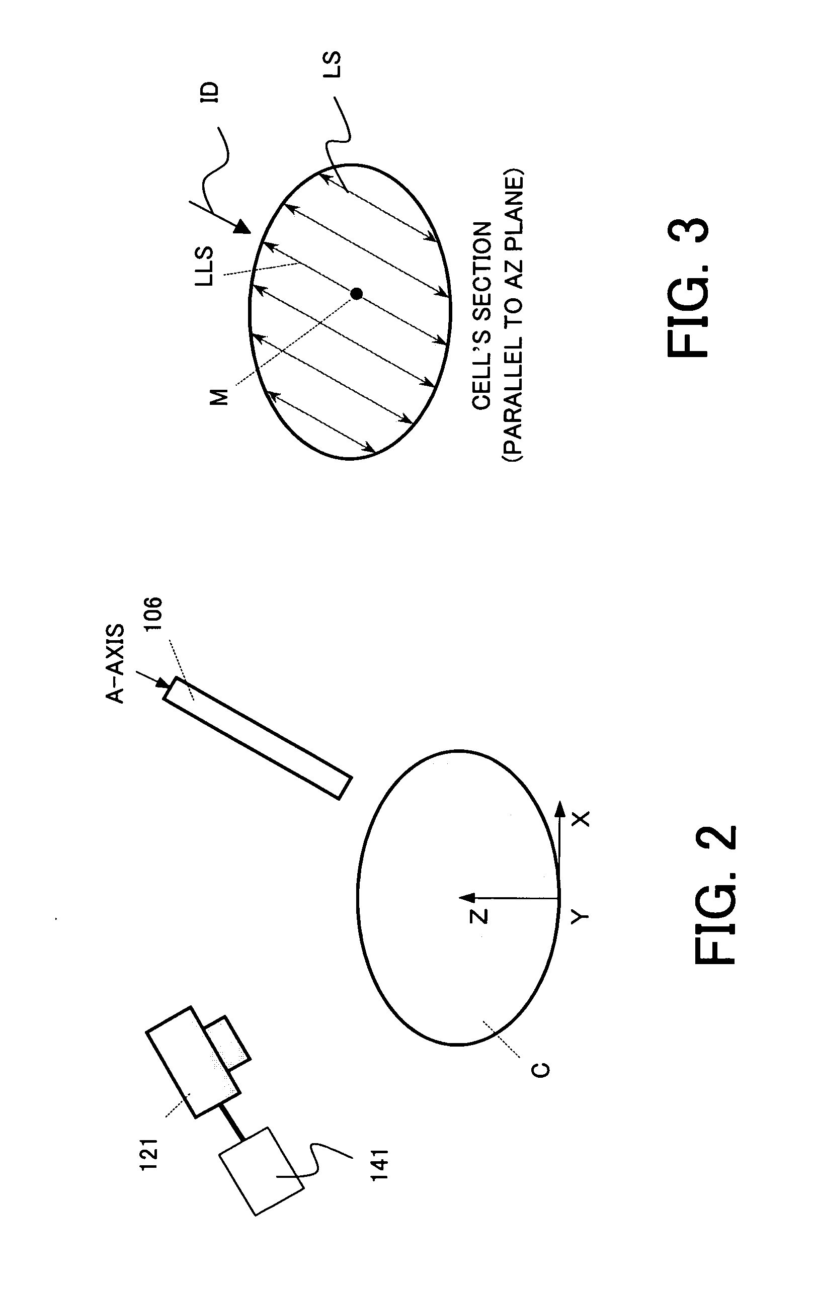
[0010] An injection apparatus according to one aspect of the present invention that inserts an injection needle into a target region in a minute object, and injects a predetermined material into the target region from the injection needle includes a positioning controller that determines, as an insertion direction, a direction that provides the longest length in the target region among plural directions in each of which the injection needle can be inserted into the minute object, and a moving unit that moves the injection needle along the insertion direction. According to the injection apparatus, the positioning controller sets a direction that provides a largest margin to the insertion position, stabilizing the insertion of the injection needle and an injection of the material.

Problems solved by technology

The biological and chemical approaches are not suitable for the medical application because they limit combinations between cells and introduced materials.
The manual injection thus requires a lot of time to obtain the necessary number of cells.
The conventional injection apparatus positions a capillary by setting a target position a predetermined distance above an attraction port or dish surface, and does not have any means for inserting a material into a specific region.
In a flatly deformed cell, a specific region has so thin depending upon the capillary's insertion direction that an insertion becomes difficult, for example, the capillary pierces the specific region.

Method used


Image

  • Injection apparatus and method
  • Injection apparatus and method
  • Injection apparatus and method

Examples


Embodiment Construction

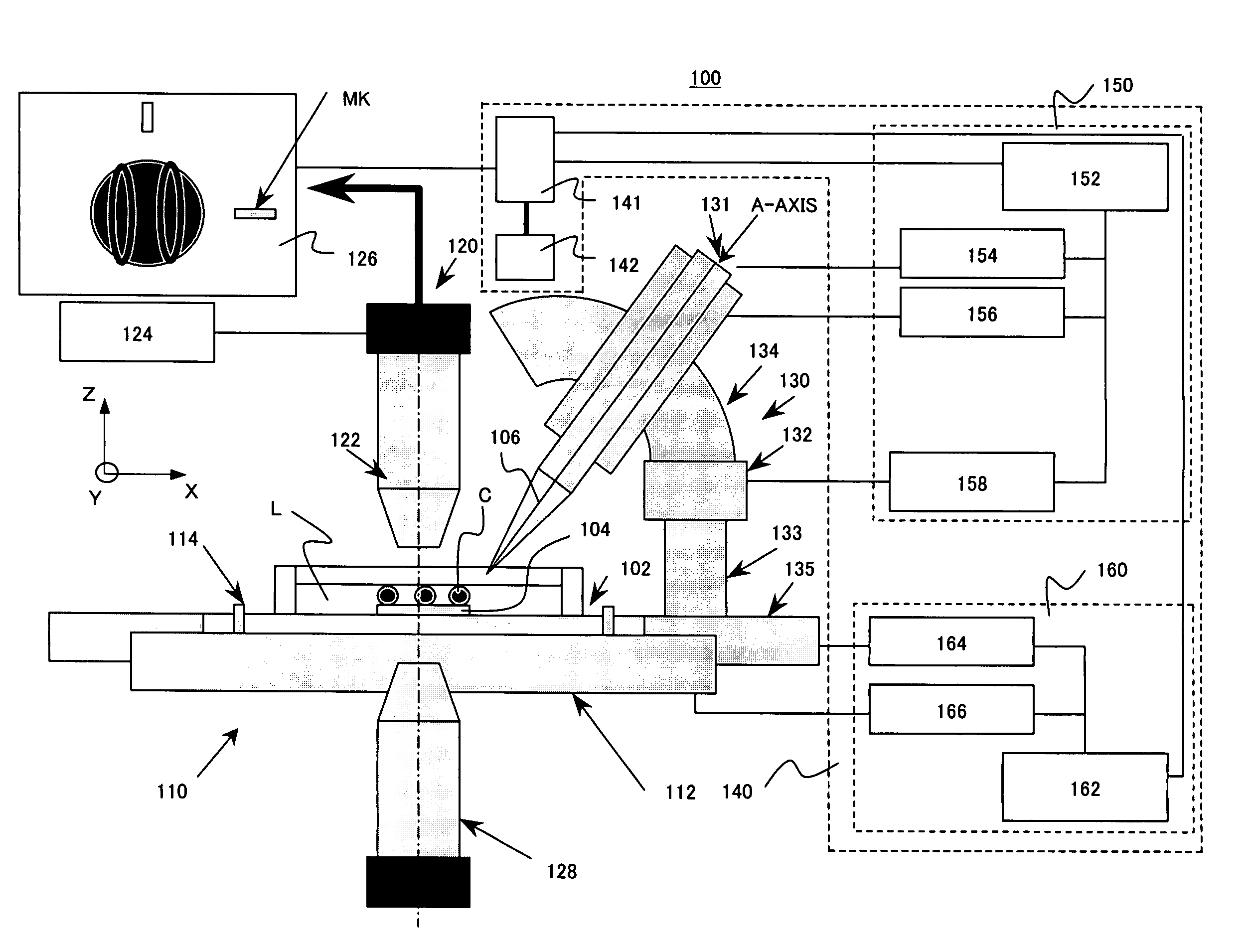
[0035] A description will now be given of an injection apparatus 100 according to one embodiment of the present invention, with reference to the accompanying drawings. The injection apparatus 100 injects a predetermined material into a minute object applicable to the present invention, such as a cell and a colloid, using a capillary. The minute object spreads and can float in a fluid or liquid L. The fluid L is, for example, cell suspension and medium. Here, FIG. 1 is a schematic sectional view of the injection apparatus 100. The injection apparatus 100 includes, as shown in FIG. 1, a laboratory dish 102, a capturing base 104, a capillary 106, a dish support system 110, an observation system 120, a capillary driving system 130, and a control system 140.

[0036] The dish 102 is a container in light gray in FIG. 1 that houses the capturing base 104, the fluid L, and plural cells C. The dish 102 is a cylindrical liquid bath that houses the fluid L and the plural cells C that float in th...


PUM


Abstract

An injection apparatus that inserts an injection needle into a target region in a minute object, and injects a predetermined material into the target region from the injection needle includes a positioning controller that determines, as an insertion direction, a direction that provides the longest length in the target region among plural directions in each of which the injection needle can be inserted into the minute object, and a moving unit that moves the injection needle along the insertion direction.

Description

[0001] This application claims the right of a foreign priority based on Japanese Patent Application No. 2005-369470, filed on Dec. 22, 2005, which is hereby incorporated by reference herein in its entirety as if fully set forth herein. BACKGROUND OF THE INVENTION [0002] The present invention relates generally to an injection apparatus or a microinjection apparatus that injects a material into a minute object, such as a cell and a colloid, via a capillary. The present invention is suitable, for example, for an injection apparatus that captures minute floating cells and injects a material into them via a capillary in a drug discovery system that investigates reactions of biogenetic cells, such as leukocytes' antibody generations, for use with a medical field. The “drug discovery system,” as used herein, generally means a system that processes a cell, e.g., injects extrinsic gene and medication solutions using a fine needle or a capillary into a cell, then cultivates each processed cel...

Claims


Application Information

Patent Timeline
IPC IPC(8): A61B17/00A61M5/00A61D1/04
CPCC12M35/00
Inventor NISHIYAMA, SHUSAKUNISHIO, CHIKARA
Owner FUJITSU LTD
Learn More