Increased projection for compacts of a rolling cone drill bit

Active Publication Date: 2005-04-28
BAKER HUGHES INC
View PDF12 Cites 43 Cited by
  • Summary
  • Abstract
  • Description
  • Claims
  • Application Information

AI Technical Summary

Benefits of technology

[0006] The bit of this invention has compacts with a slightly increased effective projection. Slightly increasing the effective projection of the compacts significantly increases the rate of penetration in formations that tend to cause bottom balling. The effective projection of the compacts is prefe

Problems solved by technology

If the projection is too long, then the compacts tend to fracture.
When drilling medium and soft formations with high percentages of clay or shale, the clay can pack between the teeth, resulting in bit balling.
Howe

Method used


Image

  • Increased projection for compacts of a rolling cone drill bit
  • Increased projection for compacts of a rolling cone drill bit
  • Increased projection for compacts of a rolling cone drill bit

Examples


Embodiment Construction

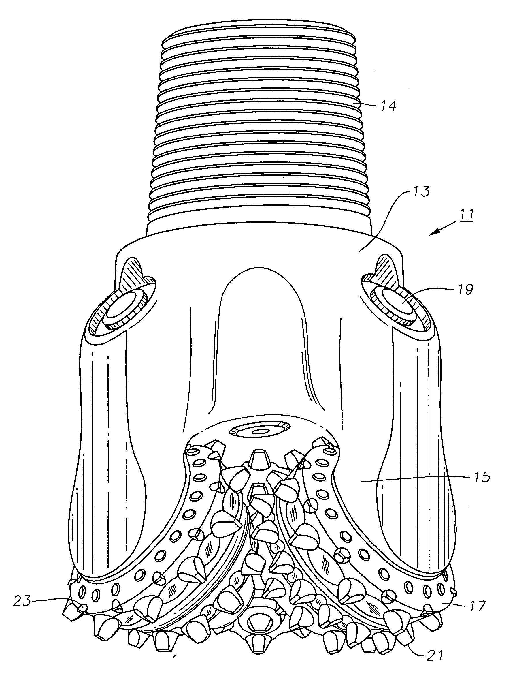
[0011] Referring to FIG. 1, bit 11 has a bit body 13 with a threaded section 14 on its upper end for attachment to a drill string. Bit body 13 has at least one bit leg 15, and in this embodiment, three bit legs 15 (only two shown). Bit legs 15 are spaced 120° apart from each about the axis of rotation of bit body 13.

[0012] A cone 17 is rotatably mounted to a depending bearing pin (not shown) extending inward from each of the bit legs 15. Cones 17 are generally conical and rotate on lubricated bearings. A lubricant compensator 19 for each bit leg 15 supplies lubricant to the bearings and reduces pressure differential between the lubricant and the hydrostatic pressure on the exterior.

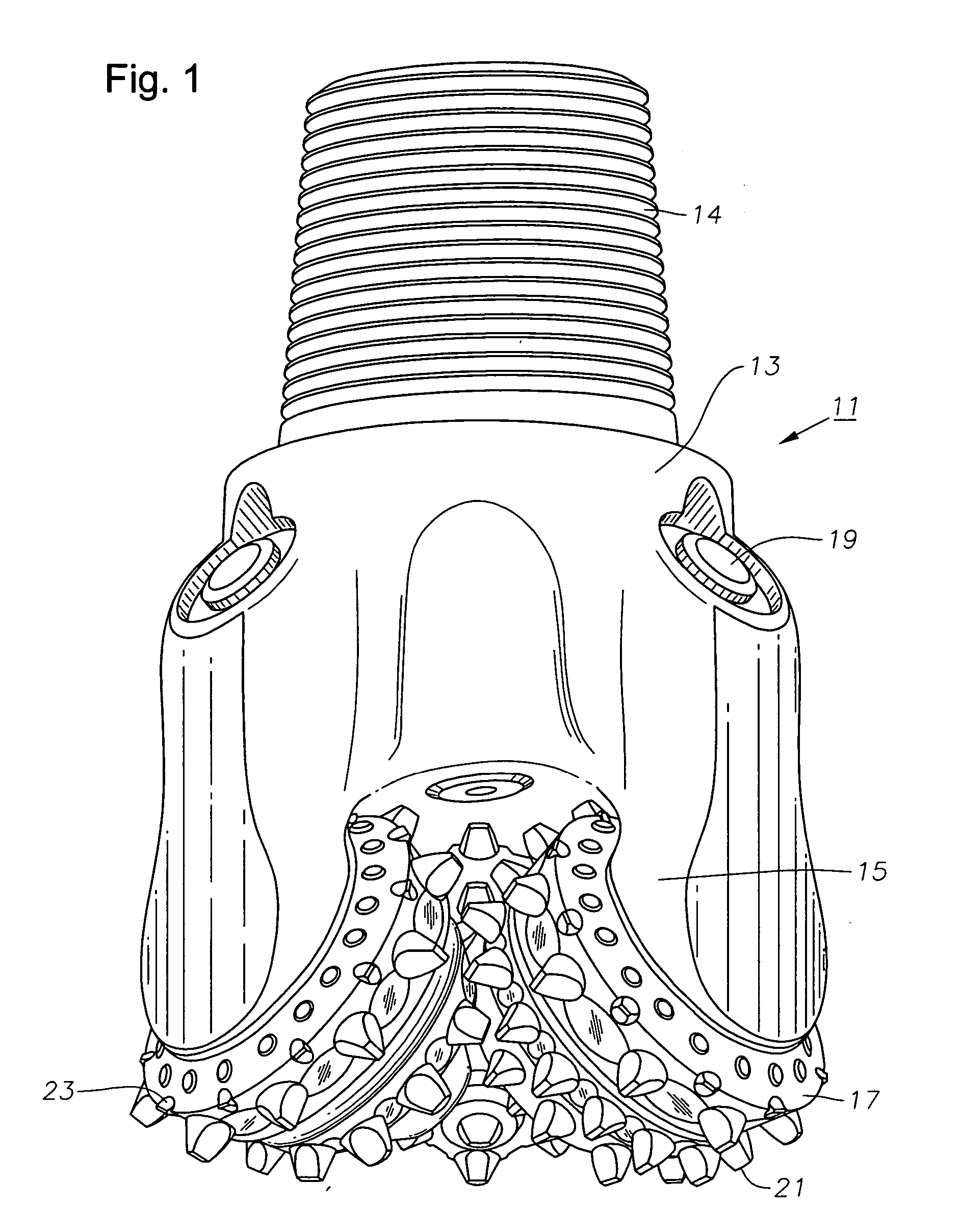
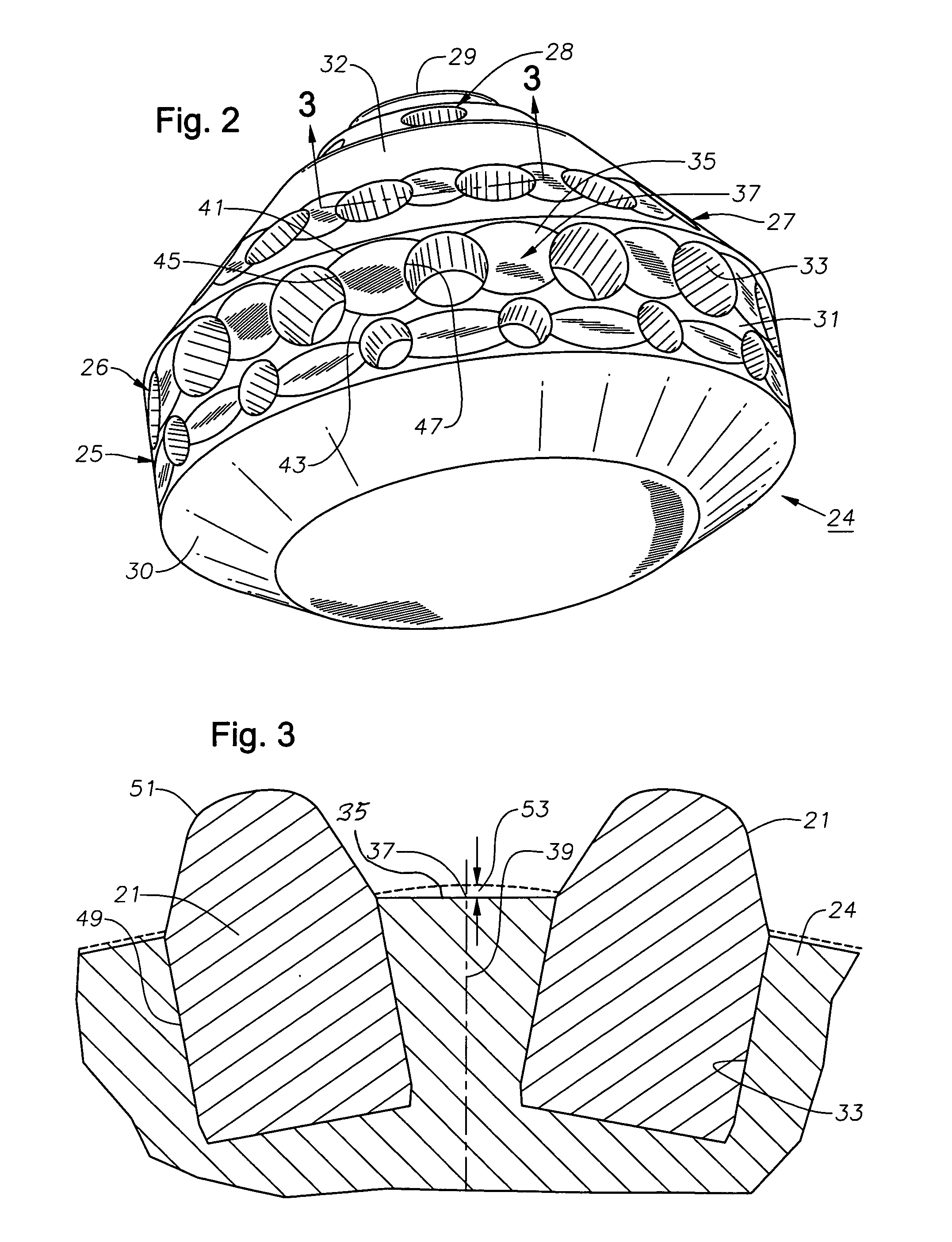
[0013] A plurality of compacts 21 are mounted to each cone 17 for disintegrating the earth formation. Compacts 21 are located in circumferential rows that extend around the axis of each cone 17. Bit legs 15 are positioned so that compacts 21 on one cone 17 will intermesh with compacts 21 on adjacent con...


PUM


Abstract

An earth boring bit has rolling cones rotatably mounted to the bit legs. Each cone has conical bands extending around the exterior. Holes are formed in each of the bands. Compacts are press-fitted into the holes, each having a cutting tip that projects from the conical band. Flats are formed in the conical bands, each flat extending between adjacent compacts. The flats cause an effective increase in projection of the compacts.

Description

FIELD OF THE INVENTION [0001] This invention relates in general to earth-boring rolling cone drill bits, and in particular to depressions milled on the surface of the cone shell between compacts to increase effective compact projection. DESCRIPTION OF THE PRIOR ART [0002] One type of earth-boring drill bit, particularly for oil and gas wells, has three rotating cones. The cones are mounted on bit legs that extend downward from a bit body. As the bit body rotates, each of the cones rotates about its own axis. Drilling mud pumped down the drill string flows out nozzles on the bit body. [0003] A plurality of teeth are formed on the cones. In the type of bit concerned herein, the teeth are hard metal compacts press-fitted into holes drilled in the cone shell. The compacts are arranged in circumferentially extending rows. Each compact has a cylindrical base and integral cutting tip, the cutting tip protruding from the cone shell. [0004] The lengths of the cutting tips and the density of ...

Claims


Application Information

Patent Timeline
IPC IPC(8): E21B10/08E21B10/16
CPCE21B10/16E21B10/08
Inventor LEDGERWOOD, LEROY W. IIIMARVEL, TIMOTHY K.
Owner BAKER HUGHES INC
Why Eureka
Try Eureka