Vehicle air conditioner

a technology for air conditioners and passenger compartments, applied in the direction of digital computer details, temperature control, optical radiation measurement, etc., can solve the problem that the air conditioning state in the passenger compartment cannot be normally controlled

Inactive Publication Date: 2005-05-19
DENSO CORP
View PDF4 Cites 19 Cited by
  • Summary
  • Abstract
  • Description
  • Claims
  • Application Information

AI Technical Summary

Benefits of technology

[0014] In the air conditioner of the present invention, the air conditioning unit can include a plurality of temperature adjusting units for adjusting the temperature of air to be blown into the passenger compartment. In this case, the first and second calculating units calculate the first and second target temperatures to be adjusted by the temperature adjusting units, as the first and the second air-conditioning control values, respectively. For example, the temperature adjusting units are arranged to correspond to seats in the passenger compartment, the non-contact temperature sensor detects the surface temperature corresponding to each of the seats of the temperature detection area, the first and the second calculating means respectively calculate the first and the second target temperatures corresponding to each of the seats, and the determining unit determines whether the obstacle exists between the non-contact temperature sensor and the temperature d

Problems solved by technology

However, in the air conditioning system, when there is an obstacle such as a fired cigarette with an abnormal temperature or a vanity mirror with a room temperature between the infrared rays temperature sensor and the passenger, the inf

Method used


Image

  • Vehicle air conditioner
  • Vehicle air conditioner
  • Vehicle air conditioner

Examples


first embodiment

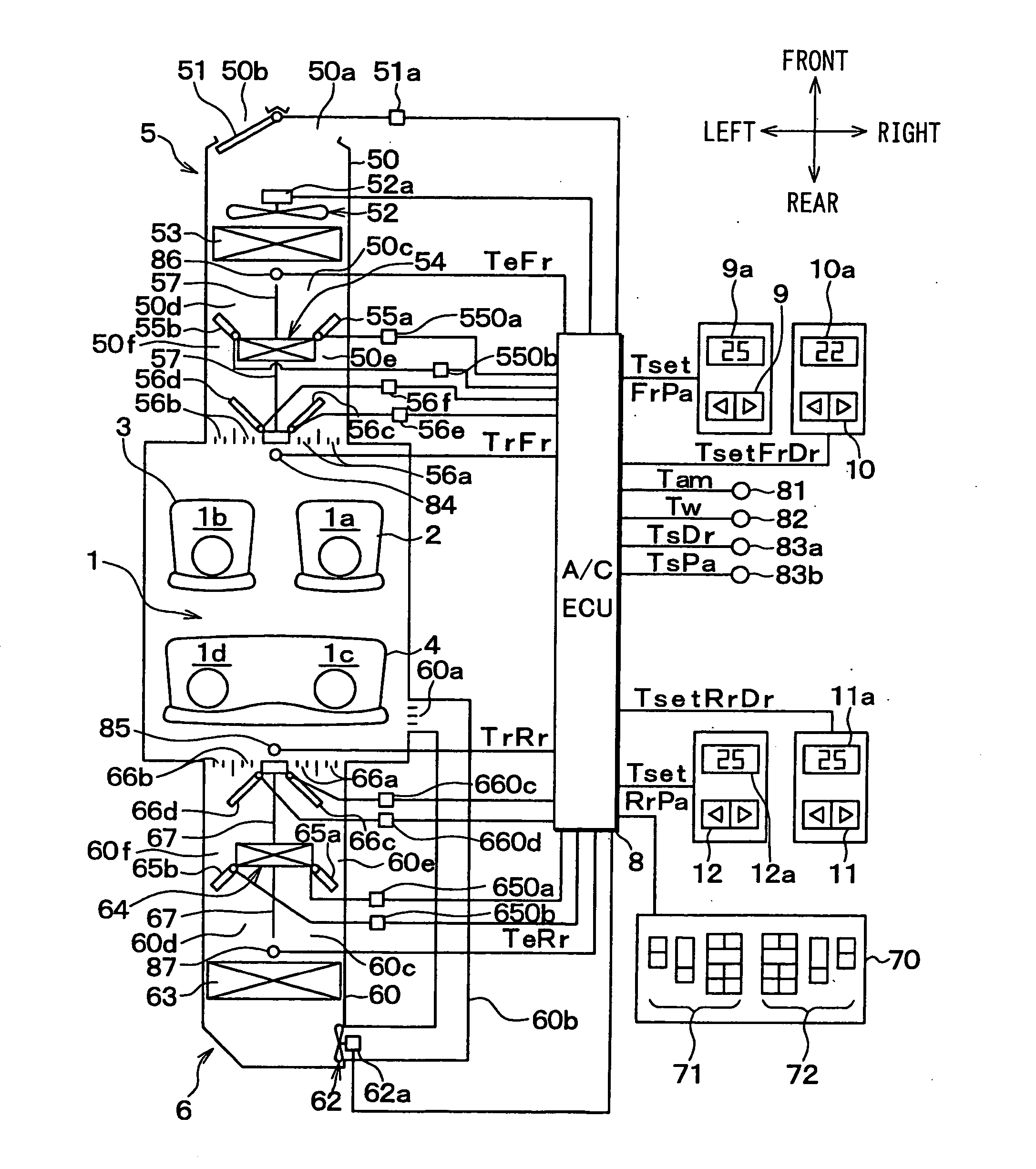
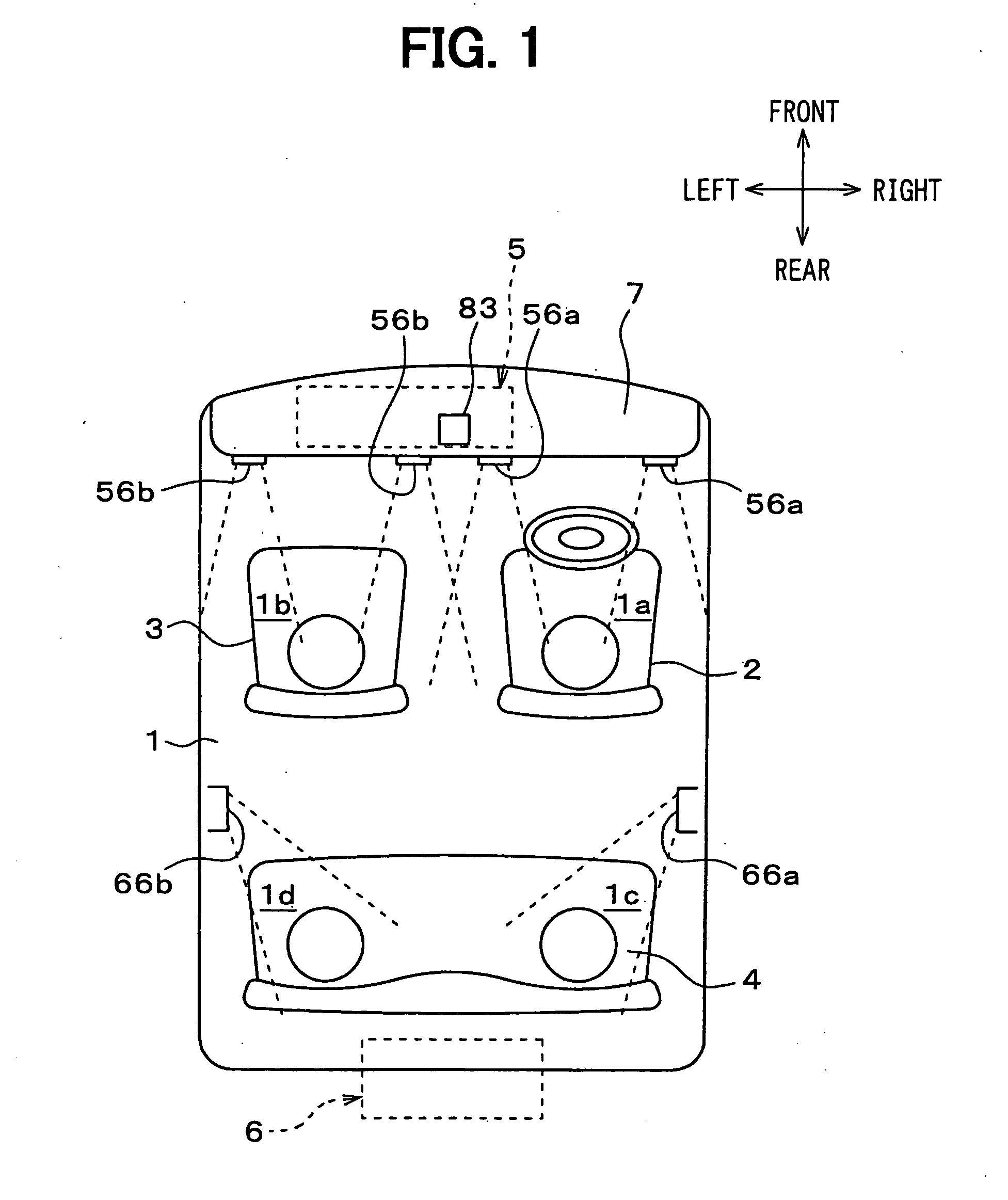
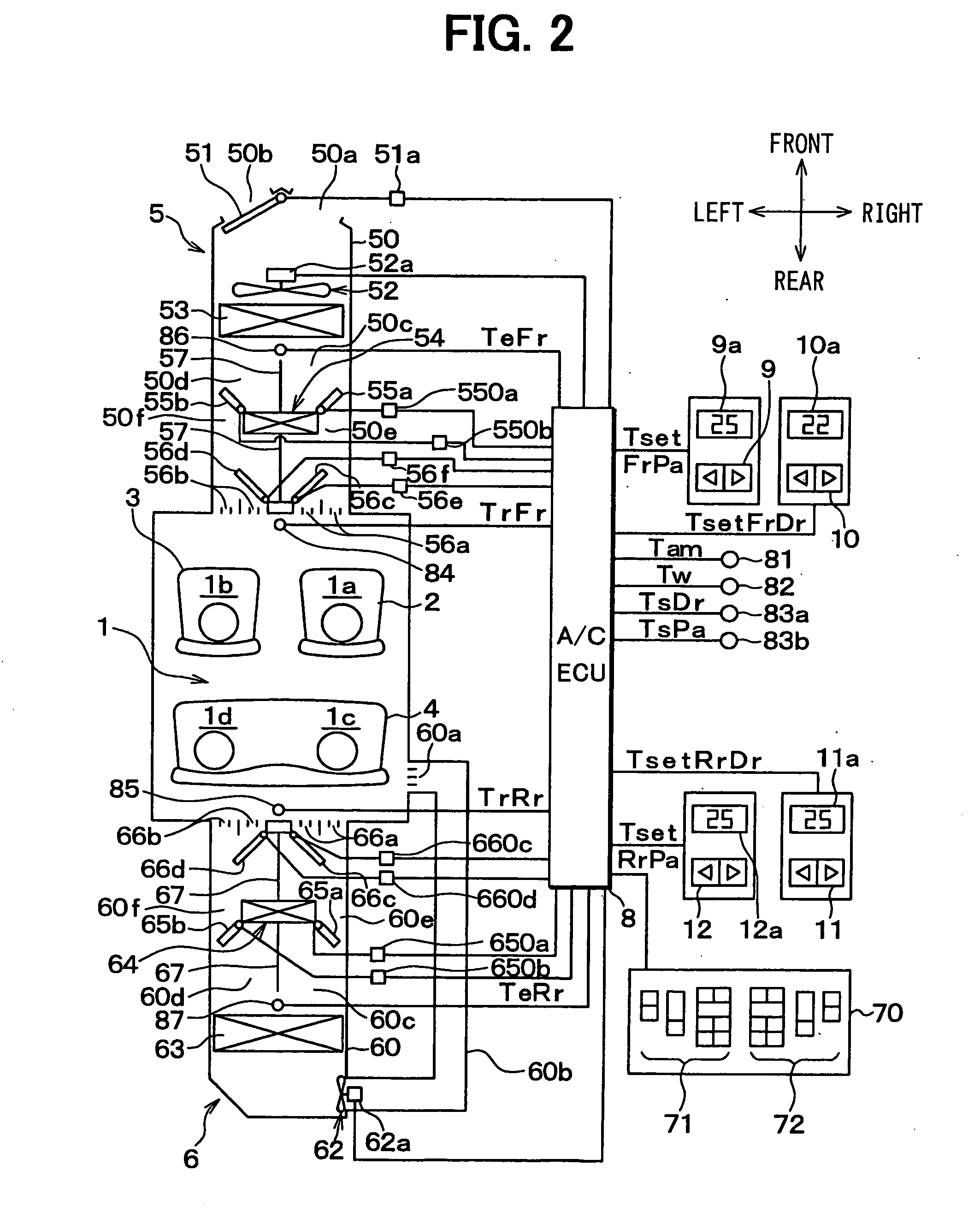
[0034] A first embodiment of the present invention will be now described with reference to FIGS. 1-10. In the first embodiment, a vehicle air conditioner independently controls each of air-conditioning operations of air conditioning zones 1a, 1b, 1c, 1d within a vehicle compartment interior (passenger compartment) 1. FIG. 1 is a schematic diagram showing the arrangement of the air conditioning zones 1a, 1b, 1c, 1d. The air conditioning zone 1a is located on a right-hand side in a front seat air conditioning zone. The air conditioning zone 1b is located on a left-hand side in the front seat air conditioning zone. The air conditioning zone 1c is located on a right-hand side in an air conditioning zone of a rear seat 4. The air conditioning zone 1d is located on a left-hand side in the air conditioning zone of the rear seat 4. The arrows of FIG. 1 show front, rear, left and right directions of the vehicle. FIGS. 1 and 2 show a vehicle state having a right steering wheel. Therefore, the...

second embodiment

[0154] In the above-described first embodiment, the target blowing-out temperature TAORrDrTR is calculated as the second air-conditioning control value based on the rear inside air temperature. In the second embodiment, a target blowing-out temperature is calculated as the second air-conditioning control value based on the passenger's clothes temperature referring to FIGS. 11, 12. In this case, the same control with that in the first embodiment will be simplified.

[0155] At first, control operation for calculating the rear right target blowing-out temperature TAORrDr is described referring to FIG. 11.

[0156] At step S200 in FIG. 11, similarly to the first embodiment, a rear right temperature TirRrDrs is calculated in accordance with the formula (5a) by using the rear right trim panel temperature TirINRrDr, the rear right window surface temperature TirWRrDr, the rear right passenger's clothes temperature TirCRrDr and the rear right passenger's skin temperature TirSRrDr.

TirRrDrs=0.3×...

third embodiment

[0179] According to the above-described first and second embodiments, the case is described in which an abnormal-temperature obstacle (e.g., ice cream or fired cigarette) exists between the non-contact temperature sensor 70 and a passenger in the passenger compartment.

[0180] In practice, obstacles having a room temperature such as a vanity mirror and a sun visor may exist between the non-contact temperature sensor 70 and the passenger. In this case, the skin temperature of the passenger and the like, which are used to calculate the target blowing-out temperatures TAORrDrIR and TAORrPaIR, cannot be accurately detected by the non-contact temperature sensor 70. If the air conditioning ECU 8 controls the rear seat air conditioning unit 6 according to the target blowing-out temperatures TAORrDrIR and TAORrPaIR, the air conditioning of the passenger compartment may be abnormally controlled.

[0181] In this embodiment, the target blowing-out temperatures TAORrDrIR and TAORrPaIR, which are ...


PUM


Abstract

In a vehicle air conditioner, a first air-conditioning control value is calculated based on a surface temperature detected by a non-contact temperature sensor in a temperature detection area of a passenger compartment. When it is determined that an obstacle exists between the temperature detection area and the non-contact temperature sensor, a second air-conditioning control value is calculated according to a temperature information that is influenced less by the obstacle than the detected surface temperature. When it is determined that the obstacle does not exist, an air conditioning state of the passenger compartment is controlled based on the first air-conditioning control value. When it is determined that the obstacle exists, the first air-conditioning control value is corrected to approach the second air-conditioning control value to calculate a corrected air-conditioning control value, so that the air conditioning state can be controlled satisfactorily.

Description

CROSS REFERENCE TO RELATED APPLICATION [0001] This application is based on Japanese Patent Applications No. 2003-386979 filed on Nov. 17, 2003 and No. 2004-239670 filed on Aug. 19, 2004, the disclosure of which is incorporated herein by reference. FIELD OF THE INVENTION [0002] The present invention relates to a vehicle air conditioner having a non-contact temperature sensor that detects a surface temperature of a passenger within a passenger compartment in non-contact so that an air conditioning state in the passenger compartment is controlled. BACKGROUND OF THE INVENTION [0003] In an air conditioning system for a vehicle, a surface temperature (e.g., face skin temperature of a passenger) in a temperature detection area of a passenger compartment is detected by a non-contact temperature sensor (e.g., infrared rays temperature sensor). According to the surface temperature, an air conditioning state in the passenger compartment is controlled to provide a comfortable air conditioning t...

Claims


Application Information

Patent Timeline
IPC IPC(8): B60H1/00G01K7/42G05D23/00
CPCB60H1/00792G01K7/42B60H2001/3471B60H1/00742B60H1/3428G01K2201/02
Inventor ICHISHI, YOSHINORIKUMADA, TATSUMI
Owner DENSO CORP
Why Eureka
Try Eureka