Electrostatic actuator and liquid droplet ejecting head having stable operation characteristics against environmental changes

a technology of which is applied in the field of electrostatic actuator and liquid droplet ejecting head, which can solve the problems of increasing the size and cost of the head, degrading image quality, and increasing the cost of products

Inactive Publication Date: 2005-05-19
RICOH KK
View PDF0 Cites 128 Cited by
  • Summary
  • Abstract
  • Description
  • Claims
  • Application Information

AI Technical Summary

Benefits of technology

[0029] Accordingly, it is a general object of the present invention to provide an electrostatic actuator and a liquid droplet ejecting head in which the above-described disadvantages are eliminated.

Problems solved by technology

There arises another problem, however, in the case of employing the configuration that does not allow gas outside the liquid droplet ejecting head to enter and exit from the vibration chambers 121 and a space communicating therewith (hereinafter referred to collectively as an actuator chamber).
This results in the degradation of image quality.
According to the first prior art, however, storage means for storing the relationship between pressure and driving voltage waveform for compensating for a variation in the ink-jet characteristics and control means are further required in addition to the pressure detecting means, thus inevitably increasing the cost of products.
Therefore, unlike the method of providing a pressure sensor, for instance, which method cannot be expected in principle to produce a desired effect, the ink-jet head of the second-prior art is expected to produce a sufficient effect.
This configuration, however, also includes another problem due to the fact that the rigidity of the displaceable plate is sufficiently lower than that of each diaphragm.
As a result, a larger area is required as a space for the pressure compensation chamber, thus increasing the size and cost of the head and leading to an increase in the size of a printer using the head.
Thus, in the conventional electrostatic actuator and the ink-jet head using the same of the second prior art, the sticking of the displaceable plate cannot be prevented by reducing the distance between the displaceable plate and its opposing surface without incurring an unnecessary increase in the size of the head.
That is, the stable ejection or operation characteristics cannot be obtained.
Further, if moisture adheres to the surface of the diaphragm, the diaphragm may adhere to the electrode through liquid bridging, thus causing ejection failure.
Furthermore, when the diaphragm is driven continuously, the vibration chamber may gradually lose the gas inside so as to enter a depressurized state.
Then, even if no voltage is applied to the electrode, the diaphragm may deflect toward the electrode side never to return to its equilibrium position, thus resulting in an insufficient amount of or insufficient pressure for ink ejection.
However, in the case of hermetically sealing the vibration chamber interposed between the diaphragm and the electrode in an environment, for instance, where the atmospheric pressure is extremely different from its normal state as in highlands where the atmospheric pressure is lower than its normal value, the diaphragm is kept deflected toward the pressure liquid chamber side by the pressure difference between the pressure inside the vibration chamber and the low external pressure, thus resulting in ejection failure.
However, the addition of the pressure detecting means or the large-area pressure control means adds to the cost of the head and makes chip downsizing and integration difficult.

Method used


Image

  • Electrostatic actuator and liquid droplet ejecting head having stable operation characteristics against environmental changes
  • Electrostatic actuator and liquid droplet ejecting head having stable operation characteristics against environmental changes
  • Electrostatic actuator and liquid droplet ejecting head having stable operation characteristics against environmental changes

Examples


first embodiment

[0081] In the following description, an electrostatic liquid droplet ejecting head employs individual electrodes and diaphragms opposing each other with air gaps formed therebetween. A potential difference is provided between the diaphragms serving as a common electrode and each individual electrode so that-the diaphragms deflect to generate pressure.

[0082] In the case of giving a more detailed description using mathematical expressions, a deformable plate whose deformation is greater than the total deformation of the diaphragms is considered as a rectangular thin plate. The nature of the deformable plate remains the same irrespective of its shape as long as the deformable plate has a greater deformation.

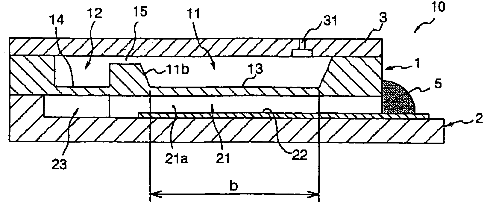
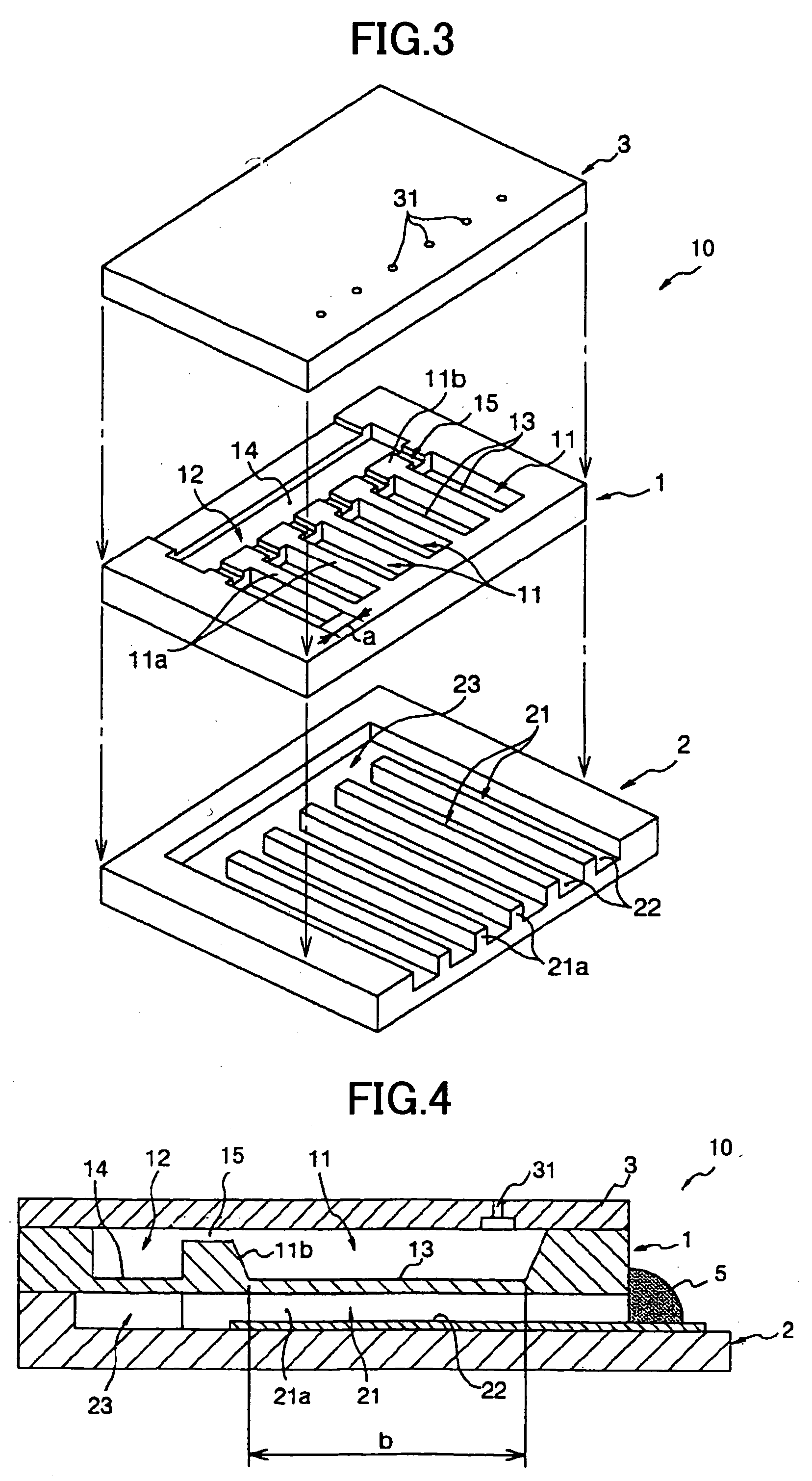
[0083]FIG. 3 is an exploded perspective view of an electrostatic liquid droplet ejecting head 10 according to a first embodiment of the present invention. FIG. 4 is a longitudinal sectional view of an actuator part of the liquid droplet ejecting head 10 in an assembled state.

[008...

second embodiment

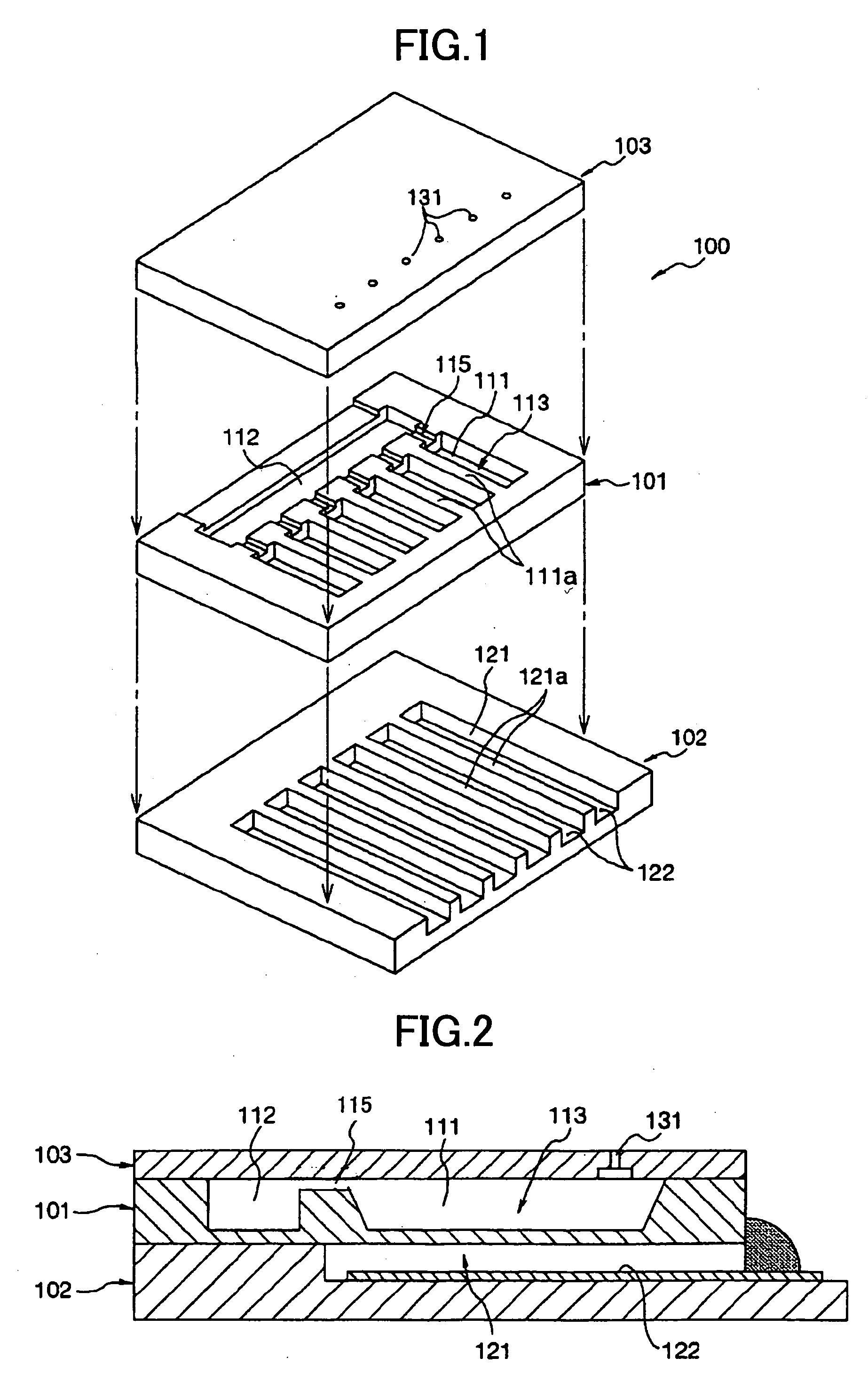
[0122] A description will be given, with reference to FIGS. 7 through 11, of an ink-jet head according to a second embodiment of the present invention. FIG. 7 is an exploded perspective view of the ink-jet head. FIG. 8 is a sectional view of a pressure liquid chamber part of the ink-jet head taken along the length of a diaphragm 210. FIG. 9 is a sectional view of the pressure liquid chamber part of the ink-jet head taken along the width of the diaphragm 210. FIG. 10 is a sectional view of a pressure correcting part of the ink-jet head taken along the length of a deformable plate 214. FIG. 11 is a plan view of the pressure correcting chamber side of the deformable plate 214 of the ink-jet head.

[0123] The ink-jet head of the second embodiment, which is a side-shooter-type head that ejects ink droplets from nozzle holes formed on the surface of a substrate, includes a layer structure formed by joining a channel substrate 201, an electrode substrate 202, and a nozzle substrate 203. The...

third embodiment

[0142] Next, a description will be given, with reference to FIG. 15, of an ink-jet head according to a third embodiment of the present invention. FIG. 15 is a sectional view of the pressure correcting part of the ink-jet head taken along the length of the deformable plate 214. In FIG. 15, the same elements as those of the second embodiment are referred to by the same numerals, and a description thereof will be omitted.

[0143] According to the ink-jet head of the third embodiment, the minute projections 216 are formed on the wall face 213a of the pressure correcting chamber 213, the wall face 213a opposing the deformable plate 214. By this configuration, the same effect as in the second embodiment can be produced. This configuration is employable in the case where it is impossible or difficult to form the minute projections 216 on the deformable plate 214 according to the production process.

[0144] In the case of providing minute projections also to the upper surfaces of the electrod...


PUM


Abstract

A liquid droplet ejecting head includes: one or more nozzle holes ejecting liquid droplets; one or more pressure liquid chambers communicating with the nozzle holes and containing liquid to be ejected; a common liquid chamber communicating with the pressure liquid chambers; one or more diaphragms each forming a wall face of the corresponding pressure liquid chamber; one or more vibration chambers containing air gaps provided in contact with the diaphragms on the opposite side from the pressure liquid chambers; and one or more electrodes provided to oppose the diaphragms through the air gaps. The liquid droplet ejecting head further includes: a deformable plate whose deformation is greater than the total deformation of the diaphragms, the deformable plate forming a wall face of the common liquid chamber, and a pressure correcting chamber provided across the deformable plate from the common liquid chamber so as to communicate with the vibration chambers.

Description

TECHNICAL FIELD [0001] The present invention generally relates to ink-jet recording, and more particularly to an electrostatic actuator, a liquid droplet ejecting head, an ink (liquid supplying) cartridge, an ink-jet recording apparatus, and a micropump. BACKGROUND ART [0002] Of the ink-jet recording apparatuses that perform recording on a recording medium by ejecting ink droplets directly onto the recording medium from nozzles, those of an on-demand type that eject ink only when necessary do not require a mechanism for collecting ink. Therefore, the on-demand-type ink-jet recording apparatuses can be reduced in cost and size, and have features that can support color recording. [0003] The ink-jet recording apparatuses are employed as image-recording apparatuses or image-forming apparatuses such as printers, facsimile machines, copiers, and plotters. An ink-jet head, which is a liquid droplet ejecting head employed in the ink-jet recording apparatuses, includes: one or a plurality of...

Claims


Application Information

Patent Timeline
Patent Type & Authority Applications(United States)
IPC IPC(8): B41J2/14B41J2/175F04B43/04
CPCB41J2/14314F04B43/043B41J2/1752B41J2/17596
Inventor TANAKA, SHINJI
Owner RICOH KK
Why Eureka
Try Eureka