Busbar molded article, process for manufacturing the same and electronic unit

a technology of molded articles and electronic units, applied in the direction of contact member manufacturing, connection contact member material, connection device connection, etc., can solve the problems of inability to precisely bend the terminal parts, inability to meet automation efficiency problems, and inability to meet mass production, so as to achieve efficient bending

Active Publication Date: 2005-05-26
YAZAKI CORP
View PDF6 Cites 12 Cited by
  • Summary
  • Abstract
  • Description
  • Claims
  • Application Information

AI Technical Summary

Benefits of technology

[0015] It is therefore an objective of the present invention to solve the above problem and to provide a busbar molded article, by which the interference between the mold that moves up and down and the resin band can be prevented from occurring and the bending can be carried out efficiently precisely, a method of manufacturing such a busbar molded article, and an electronic unit having such a busbar molded article.

Problems solved by technology

However, as for the conventional examples described above, the following problems exist.
Therefore, when a plurality of the terminal parts 50 arranged in a row laterally are simultaneously bent, a precise bending of the terminal parts might not be carried out due to a problem of the stiffness of the bending machine.
Further, since the bending method of the terminal parts 50 is complicated, the method is not suitable to automation having a problem of efficiency.
In the second conventional example, although the terminal part 55 can be bent with a simple method by using a twisting jig, a plurality of the terminal parts 55 cannot be simultaneously bent, causing low efficiency being not suitable for mass production.
Moreover, when an obstacle such as a rising terminal part or projection exists in the direction in which the table 66 is slid, the table 66 cannot be slid in the direction crossing at right angles with the acting direction of the mold 63 after the terminal part 62 is bent, causing a problem that the busbar molded article 60 cannot be removed from the pressing machine after the bending.
In the fourth conventional example, since a method of bending simultaneously a plurality of the terminal parts arranged in a line is not provided, therefore there is a problem that the efficiency of the bending is low.

Method used


Image

  • Busbar molded article, process for manufacturing the same and electronic unit
  • Busbar molded article, process for manufacturing the same and electronic unit
  • Busbar molded article, process for manufacturing the same and electronic unit

Examples


Embodiment Construction

[0045] In the following, the preferred embodiments of the present invention will be explained with reference to the attached drawings.

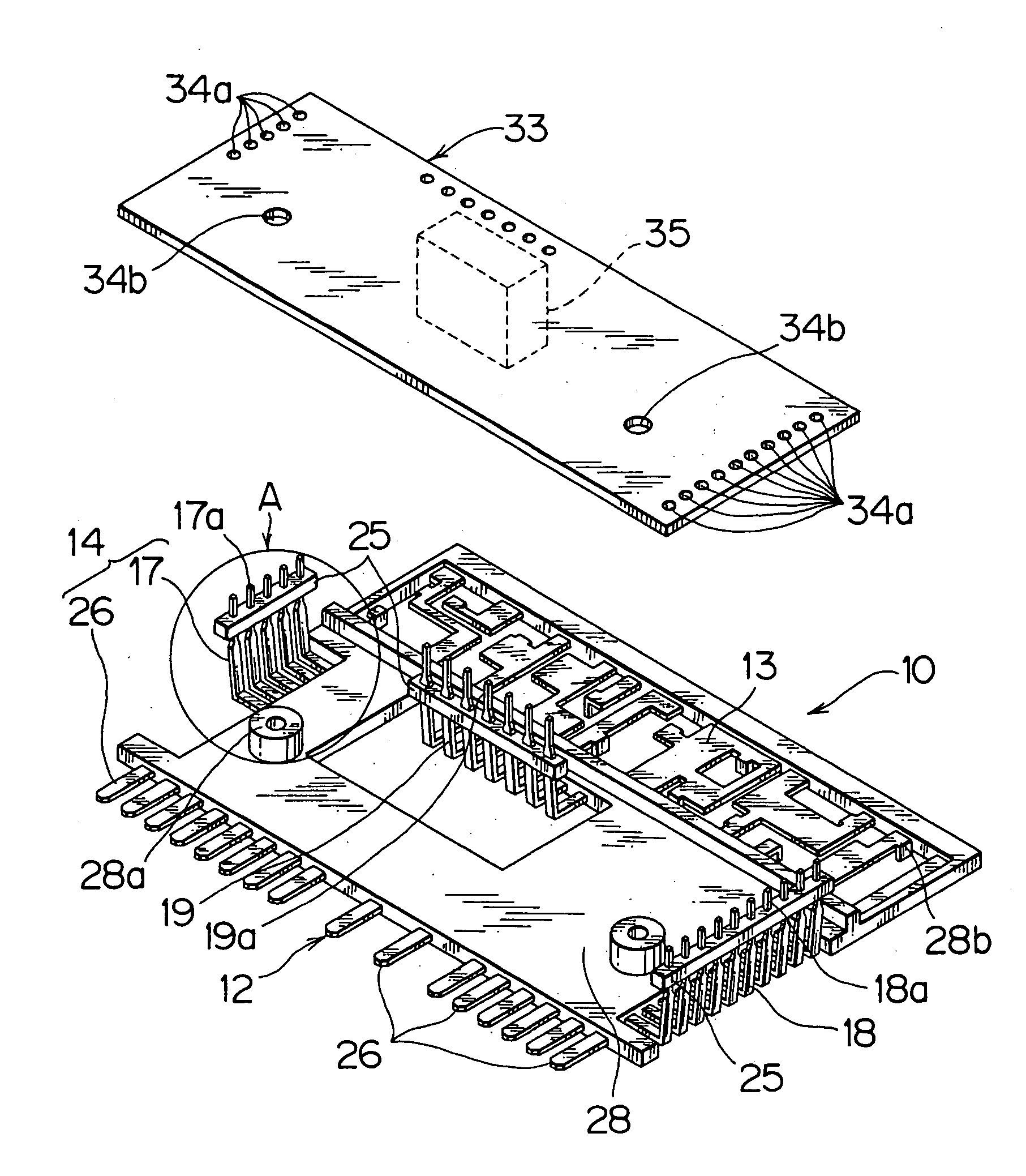
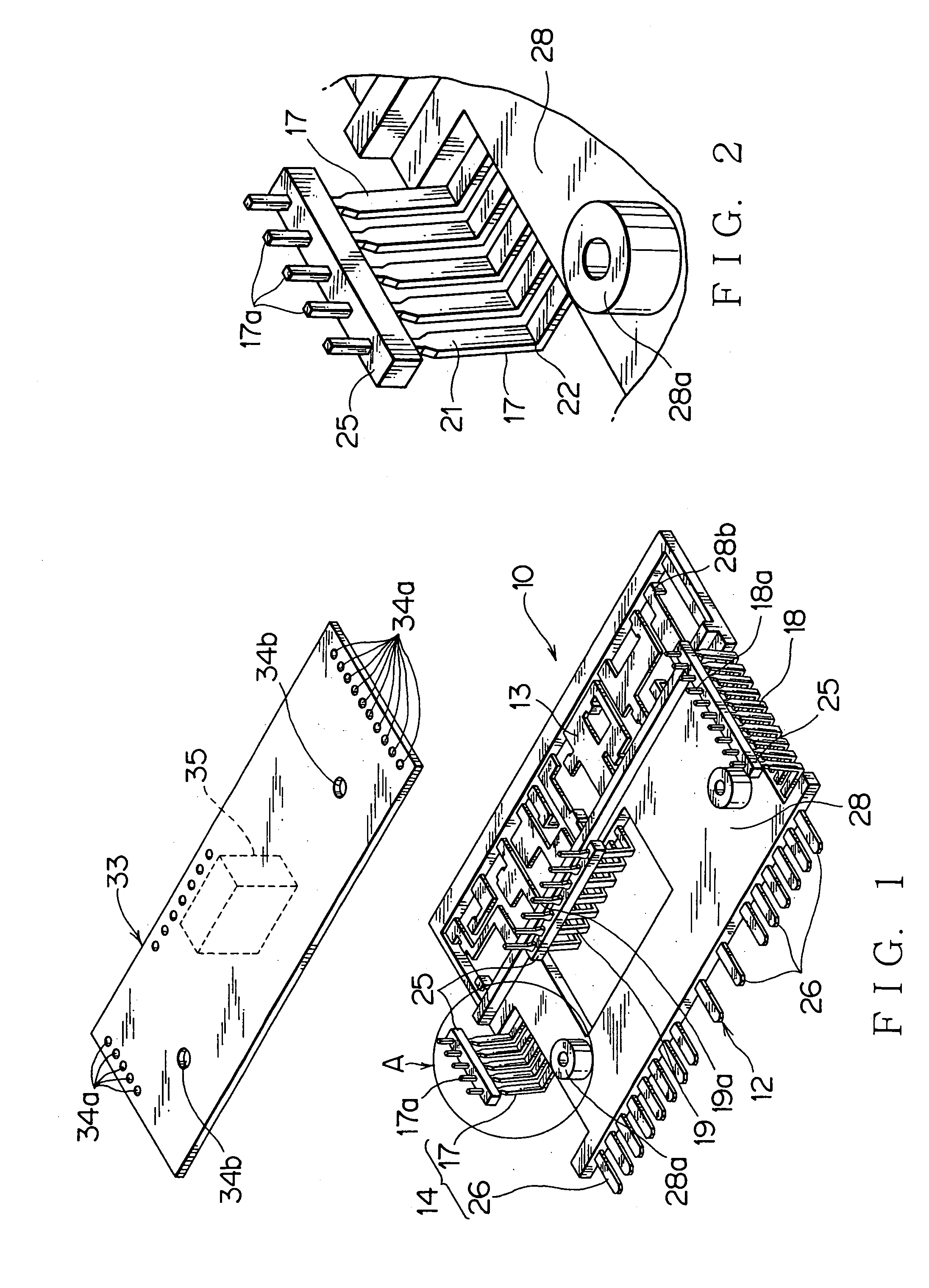
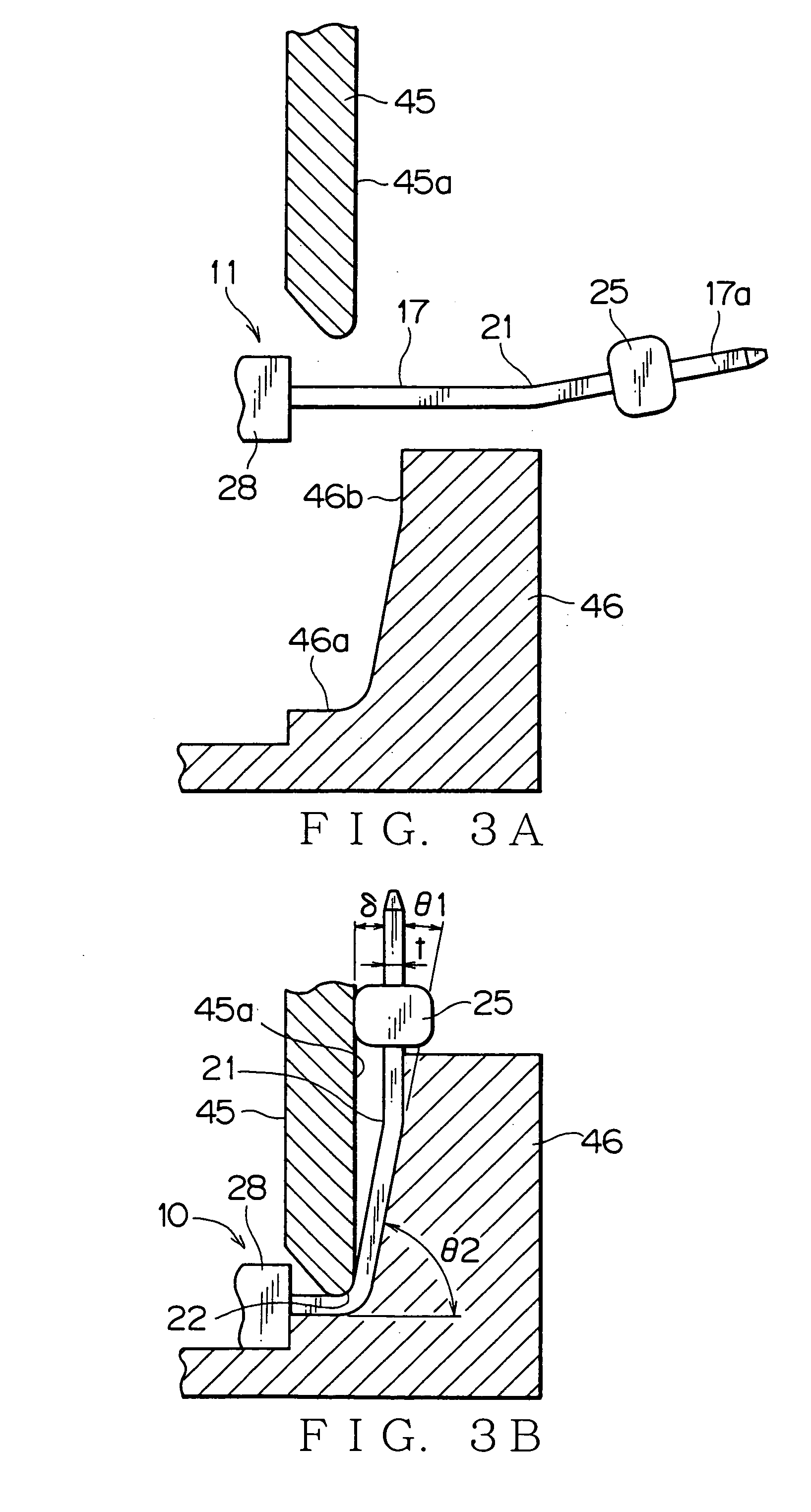
[0046]FIGS. 1-3B show a preferred embodiment of a busbar molded article and a process for manufacturing the busbar molded article according to the present invention. FIG. 4 shows a preferred embodiment of an electronic unit according to the present invention.

[0047] The busbar molded article is a molded article, which has been stamped out by using a pressing machine (not shown in the figure), bent according to the need and insert-molded together with an insulating synthetic resin, and is used as a constitutional component of an electric junction box or electronic unit. The busbar molded article 10 according to the preferred embodiment is used in an electronic unit 30 shown in FIG. 4.

[0048] The busbar molded article 10 according to the preferred embodiment can prevent the interference between a mold 45 of a pressing machine, which mold 45 moves up an...


PUM


Abstract

The busbar molded article 10 includes: a busbar 12 formed by being stamped out from an electrically conductive substrate; a plurality of terminal parts 17 lined up on the busbar; and a resin band 25 for alignment-correction formed on the side of an end of a plurality of the terminal parts 17, wherein each terminal part 17 is provided with: a first bent part 21 bent by a small bend angle θ1; and a second bent part 22 bent by a large bend angle θ2 by stamping with a pressing machine, the second bent part 22 being formed nearer to the side of a base of each terminal part 17 than the first bent part 21 being formed, so that the resin band 25 is offset to a mold 45 that moves up and down of the pressing machine.

Description

BACKGROUND OF THE INVENTION [0001] (1) Field of the Invention [0002] The present invention relates to a busbar molded article including a busbar stamped out from an electrically conductive substrate in a specific circuit pattern and an electrically conductive substrate formed in one piece with the busbar, and to a process for manufacturing the busbar molded article. The present invention also relates to an electronic unit having the busbar molded article, which electronic unit controls an auxiliary machine of a motor vehicle such as a wiper, washer, front light, foglamp and air-conditioner. [0003] (2) Description of the Related Art [0004] An example of such a conventional busbar molded article and a conventional process for manufacturing the busbar molded article is shown in FIGS. 5-7 (Japanese Patent Application Laid-Open No. 2000-77152 and Japanese Patent Application Laid-Open No. 2001-251729). [0005] A conventional example (Japanese Patent Application Laid-Open No. 2000-77152) sh...

Claims


Application Information

Patent Timeline
Patent Type & Authority Applications(United States)
IPC IPC(8): H01R43/16H02G3/16H05K7/06
CPCH01R43/16
Inventor TSUGANE, HITOSHINAKAHAMA, YOSHIHIKO
Owner YAZAKI CORP
Why Eureka
Try Eureka