Clutch or brake device formed of composite foam

a brake device and composite foam technology, applied in the direction of friction lining, ceramicware, other domestic articles, etc., can solve the problems of high carbon fiber cost, limited commercial application of these structures, high cost of carbon fiber, etc., and achieve the effects of reducing cost, reducing cost, and generally low cost of carbon foam

Inactive Publication Date: 2005-06-02
SAFRAN LANDING SYSTEMS
View PDF20 Cites 8 Cited by
  • Summary
  • Abstract
  • Description
  • Claims
  • Application Information

AI Technical Summary

Benefits of technology

[0013] The methods and apparatus of this invention provide numerous advantages. For example, the cost of carbon foam is generally lower than that of carbon fibers. Therefore, methods of this invention can significantly reduce the cost of forming substantially-dense carbon / carbon composite foams. Accordingly, a broader range of applications can now be economically justified for use of carbon / carbon composites. Further, the resulting foams can have a substantially isotropic and openly-porous structure relative to that of many materials that employ fibers. Because the composite is substantially isotropic, performance of a frictional surface comprising a foam of this invention is likely to be more uniform and consistent as the friction surface wears. The ceramic composite foams also have a relatively high permeability, thereby facilitating hydraulic flow in many wet-friction applications. Moreover, distortion from machining is reduced due to the isotropic structure, thereby promoting flatness and parallelism in machined friction surfaces. The methods of this invention also can be used to produce exceptionally dense structures with over 50% solid density, while retaining open porosity.

Problems solved by technology

They are favored for use in high-end automotive transmissions but high costs have prevented widespread utilization.
Though the above-described methods are known to produce high-quality composite structures, the commercial application of these structures is limited by the high cost of carbon fibers, processing and energy consumption.
Accordingly, the application of these methods to mass-production industries such as automobile manufacturing has thus far been greatly limited due to economic feasibility.

Method used


Image

  • Clutch or brake device formed of composite foam
  • Clutch or brake device formed of composite foam
  • Clutch or brake device formed of composite foam

Examples


Embodiment Construction

[0017] The features and other details of the method of the invention will now be more particularly described with reference to the accompanying drawing and pointed out in the claims. It will be understood that the particular embodiments of the invention are shown by way of illustration and not as limitations of the invention. The principal features of this invention can be employed in various embodiments without departing from the scope of the invention.

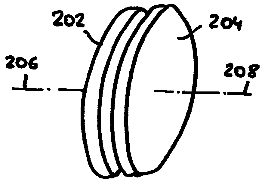
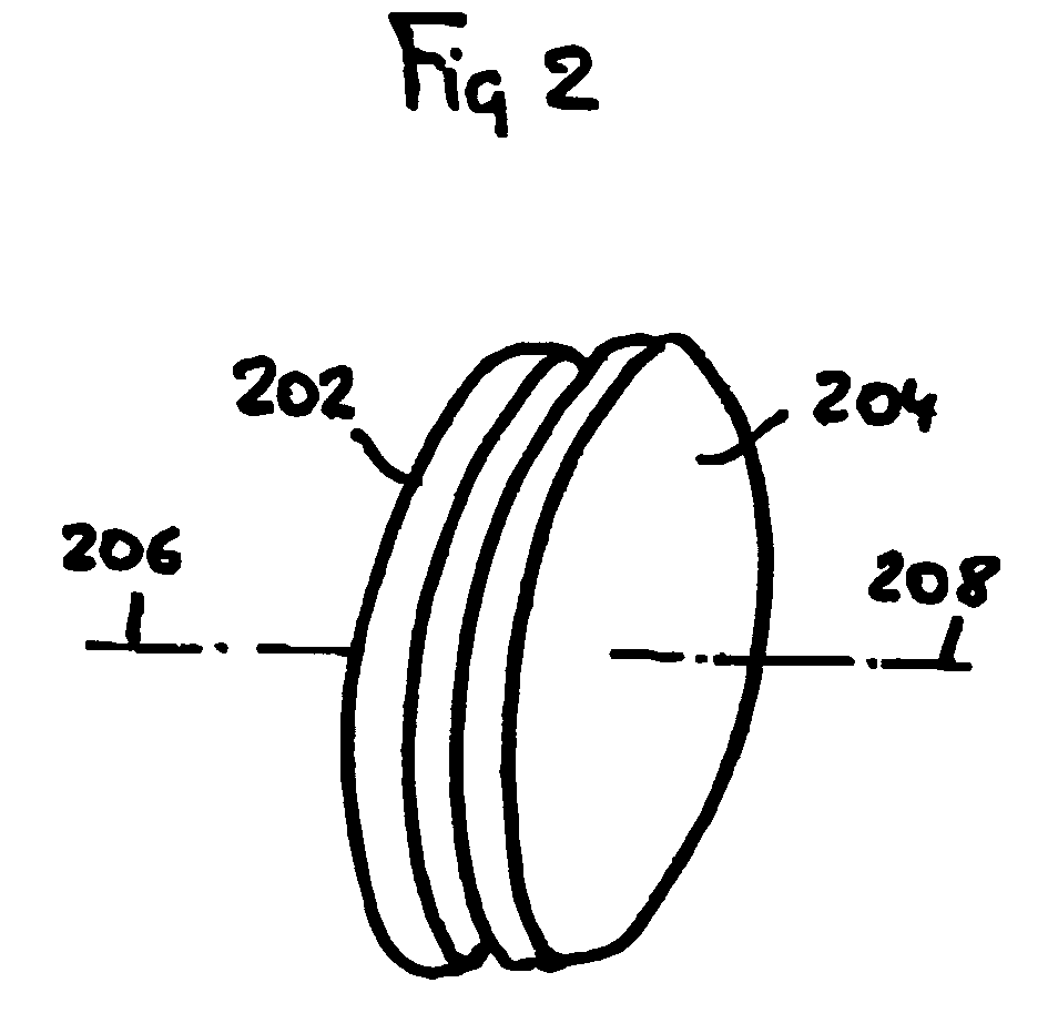
[0018] In a method of this invention, a densified composite foam is formed by depositing a coating on an open-cell reticulated foam skeleton.

[0019] In one embodiment of the method, the foam skeleton comprises carbon in the form of an open lattice of ligaments, wherein the interconnected pores defined by the lattice have diameters of about 0.5 to about 1.0 mm. The lattice has a micrographic porosity of about 100 pores per inch, a bulk density of about 0.04 g / cm3, and a surface area of about 1.6 m2 / g. In an alternate embodiment, the ...


PUM

PropertyMeasurementUnit
diametersaaaaaaaaaa
densityaaaaaaaaaa
dielectric constantaaaaaaaaaa

Abstract

An improved clutch or brake device in which at least two members are mounted for relative rotation and engagement, the members having friction material rotatable therewith, and the friction material of the members having surfaces confronting each other, characterized in that the friction material has a solid density of greater than 30% and includes an open lattice of carbon ligaments forming a network of three dimensionally interconnected cells; and a pyrolytic carbon coating on the open lattice of carbon ligaments.

Description

RELATED APPLICATIONS [0001] This application is a divisional application of U.S. application Ser. No. 10 / 675,295 filed Sep. 30, 2003; which is a divisional of U.S. application Ser. No. 09 / 857,949 filed Aug. 8, 2001, now U.S. Pat. No. 6,726,962 issued Apr. 27, 2004; which is the 371 national phase of PCT / US99 / 30140 filed Dec. 17, 1999; and claims the benefit of U.S. Provisional Application No. 60 / 112,704 filed Dec. 18, 1998, the entire contents of which are incorporated herein by reference.BACKGROUND OF THE INVENTION [0002] Relatively-dense carbon / carbon composites have been found to be highly useful in a variety of structural applications. Because of certain characteristics, such as high strength, high stiffness, light weight, high temperature resistance, and advantageous frictional properties, these composites are desirably suited for use, for example, in the aerospace and automotive brake pad industries. They are favored for use in high-end automotive transmissions but high costs ...

Claims


Application Information

Patent Timeline
Patent Type & Authority Applications(United States)
IPC IPC(8): C04B35/52C04B35/83C04B38/06F16D69/02
CPCC04B35/521Y10T428/30C04B38/0615C04B2235/3826C04B2235/3873C04B2235/48C04B2235/483C04B2235/614C04B2235/80F16D69/023F16D2250/0038C04B35/83C04B38/0051C04B38/0067C04B38/0074Y10T428/249981Y10T428/249961Y10T428/249967Y10T428/249988Y10T428/24999
Inventor LOSZEWSKI, RAYMOND C.
Owner SAFRAN LANDING SYSTEMS
Why Eureka
Try Eureka