Lens barrel and imaging device

a technology which is applied in the field of lens barrel and imaging device, can solve the problems of disadvantageous use of iris for reducing the size of the lens barrel, and achieve the effect of less noticeable unnatural variation in brightness in the taken imag

Inactive Publication Date: 2005-06-23
SONY CORP
View PDF4 Cites 6 Cited by
  • Summary
  • Abstract
  • Description
  • Claims
  • Application Information

AI Technical Summary

Benefits of technology

[0016] According to the invention where the orientational direction of the liquid-crystal light control element is substantially parallel to the shorter sides of the imaging area, even when the amount of light passing through the liquid-crystal light control element varies depending on the location in the plane of the liquid-crystal light control element, with the angle of the light emitted from the optical system and passing through the liquid-crystal light control element with respect to the direction of the thickness of the liquid crystal layer of the liquid-crystal light control element being varied depending on the location in the plane due to the reduction in size of the optical system, the influence of the variation in the amount of the light passing through the liquid-crystal light control element on the brightness in the image is reduced compared to an arrangement where the orientational direction of the liquid-crystal light control element is substantially parallel to the longer sides of the imaging area, because the variation in the amount of the light passing through the liquid-crystal light control element is smaller than that in the compared arrangement. Thus, the invention is advantageous for making the unnatural variation in brightness in the taken image less noticeable when the image is viewed.

Problems solved by technology

However, use of the iris is disadvantageous for a reduction in size of the lens barrel since blades of the iris and a mechanism for driving the iris blades occupy a considerable space.

Method used


Image

  • Lens barrel and imaging device
  • Lens barrel and imaging device
  • Lens barrel and imaging device

Examples


first embodiment

[0035] There will be described the invention with reference to the drawings.

[0036] In the first embodiment, a lens barrel according to the invention is built into an imaging device.

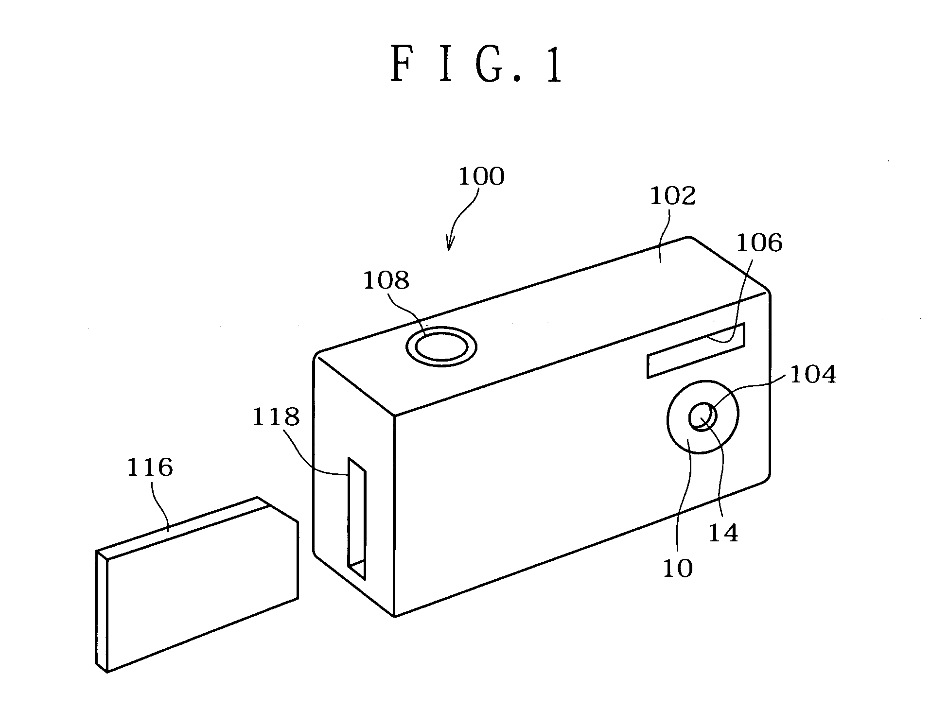
[0037]FIG. 1 is a perspective view of an imaging device according to a first embodiment of the invention, as seen from its front side.

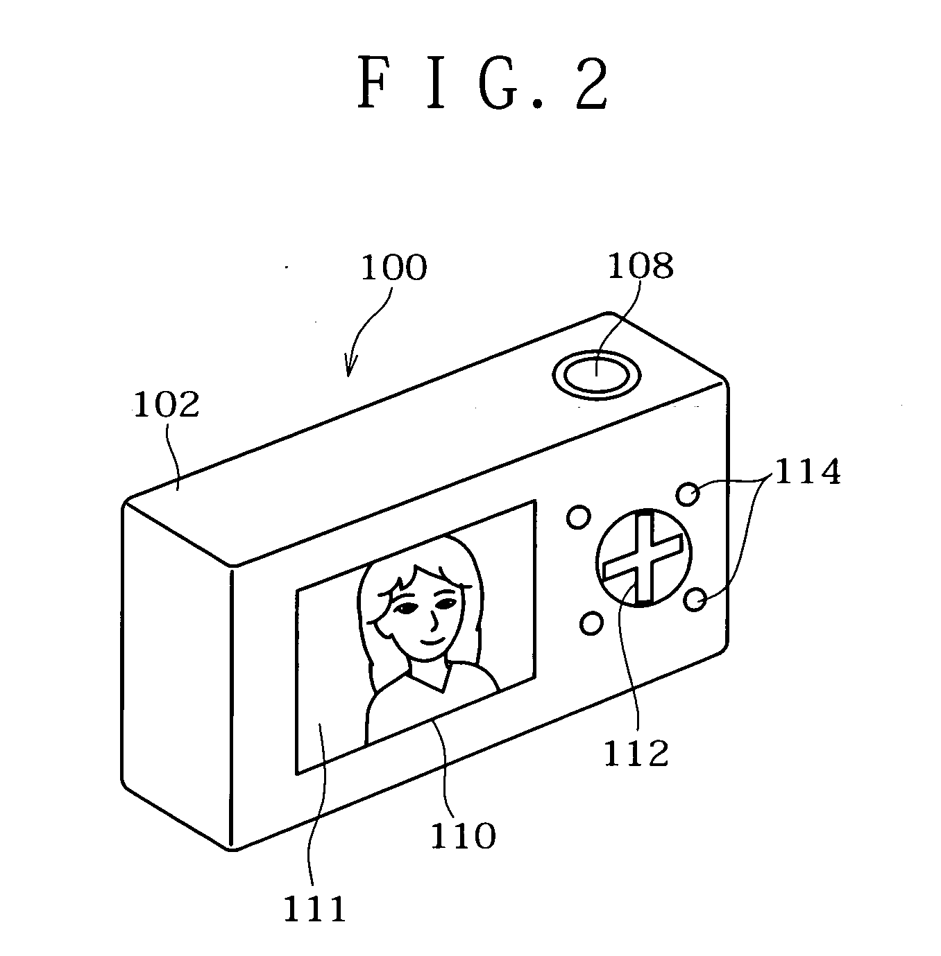
[0038]FIG. 2 is a perspective view of the imaging device of the first embodiment, as seen from its back side.

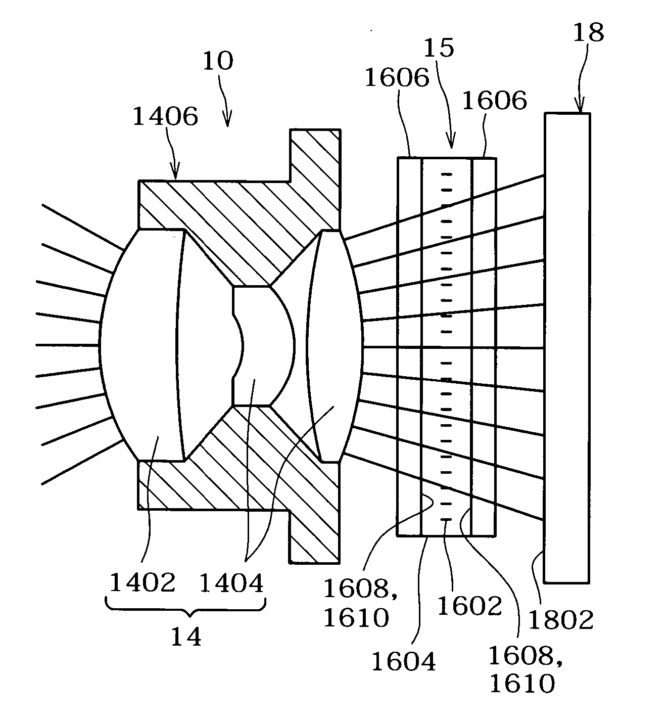
[0039]FIG. 3 is a schematic view of a lens barrel shown in FIG. 1.

[0040]FIG. 4 is a block diagram showing a control system of the imaging device.

[0041]FIG. 5 is an exploded perspective view of the lens barrel.

[0042]FIG. 6 is a cross-sectional view of the lens barrel.

[0043]FIG. 7 is an assembly diagram of a rear unit partially constituting the lens barrel including a liquid-crystal light control element and an imaging element.

[0044]FIG. 8 is a cross-sectional view of the assembly shown in FIG. 7.

[0045]FIG. 9 is an exploded perspective view of the rear unit.

[...

second embodiment

[0132]FIG. 17 is a perspective view of a mobile phone 200 according to the invention.

[0133] The mobile phone 200 comprises a manipulation portion 204 and a display portion 206 which are connected with a hinge 202. The display portion 206 has a lens barrel 10 similar to that according to the first embodiment and exposed to the external space. In an inner surface of the display portion 206, a display 208 similar to the display 110 of the first embodiment is disposed.

[0134] The mobile phone 200 has functions including one for taking an image through the lens barrel 10 in a way similar to the imaging device 100 of the first embodiment and displaying the image on the display 208, and it constitutes an imaging device according to the present invention.

[0135] Although the mobile phone 200 is different from the imaging device 100 of the first embodiment in that the direction of the shorter sides of a screen 209 of the display 208 as used in an ordinary fashion coincides with the horizonta...


PUM

PropertyMeasurementUnit
tilt angleaaaaaaaaaa
thicknessaaaaaaaaaa

Abstract

A lens barrel and imaging device advantageous for making unnatural brightness variation in an image, due to a liquid-crystal light control element, less noticeable, while reducing the size of an optical system, are disclosed. A lens barrel comprises an optical system, a rectangular planar liquid-crystal light control element, and an imaging element. An object image captured by the optical system is guided to the imaging element through the control element comprising a liquid crystal layer sealed in between a pair of alignment layers and containing rod-shaped liquid crystal molecules. A sensor unit of the imaging element has a rectangular imaging area. Light rays guided from the optical system to the imaging element diverge away from an optical axis. An orientational direction of the control element is substantially parallel to the shorter sides of the imaging area.

Description

BACKGROUND OF THE INVENTION [0001] 1. Field of the Invention [0002] The present invention relates to a lens barrel and an imaging device. [0003] 2. Description of Related Art [0004] A lens barrel of an imaging device, such as a digital camera and video camera, comprises an optical system guiding an image of an object, an imaging element disposed in an optical axis of the optical system, which may be a CCD, and light control means for adjusting an amount of light guided to the imaging element along the axis of the optical system. [0005] In many cases, an iris, which mechanically adjusts an aperture, is used as the light controlling means. However, use of the iris is disadvantageous for a reduction in size of the lens barrel since blades of the iris and a mechanism for driving the iris blades occupy a considerable space. [0006] Therefore, there has been proposed an imaging device using a liquid-crystal light control element which occupies a relatively small space. For instance, such a...

Claims


Application Information

Patent Timeline
Patent Type & Authority Applications(United States)
IPC IPC(8): G02B7/00G02F1/13G02B7/02G02F1/1335G02F1/1337G02F1/137G02F1/139G03B9/02H04N5/225H04N5/238H04N101/00
CPCG02F1/139H04N5/2254H04N5/2253H04N23/55H04N23/54
Inventor IMAI, SATOSHIMIZUSHIMA, MASAYASUSHIMIZU, SHUJISATO, YUTAKATABEI, HIROYUKI
Owner SONY CORP
Why Eureka
Try Eureka